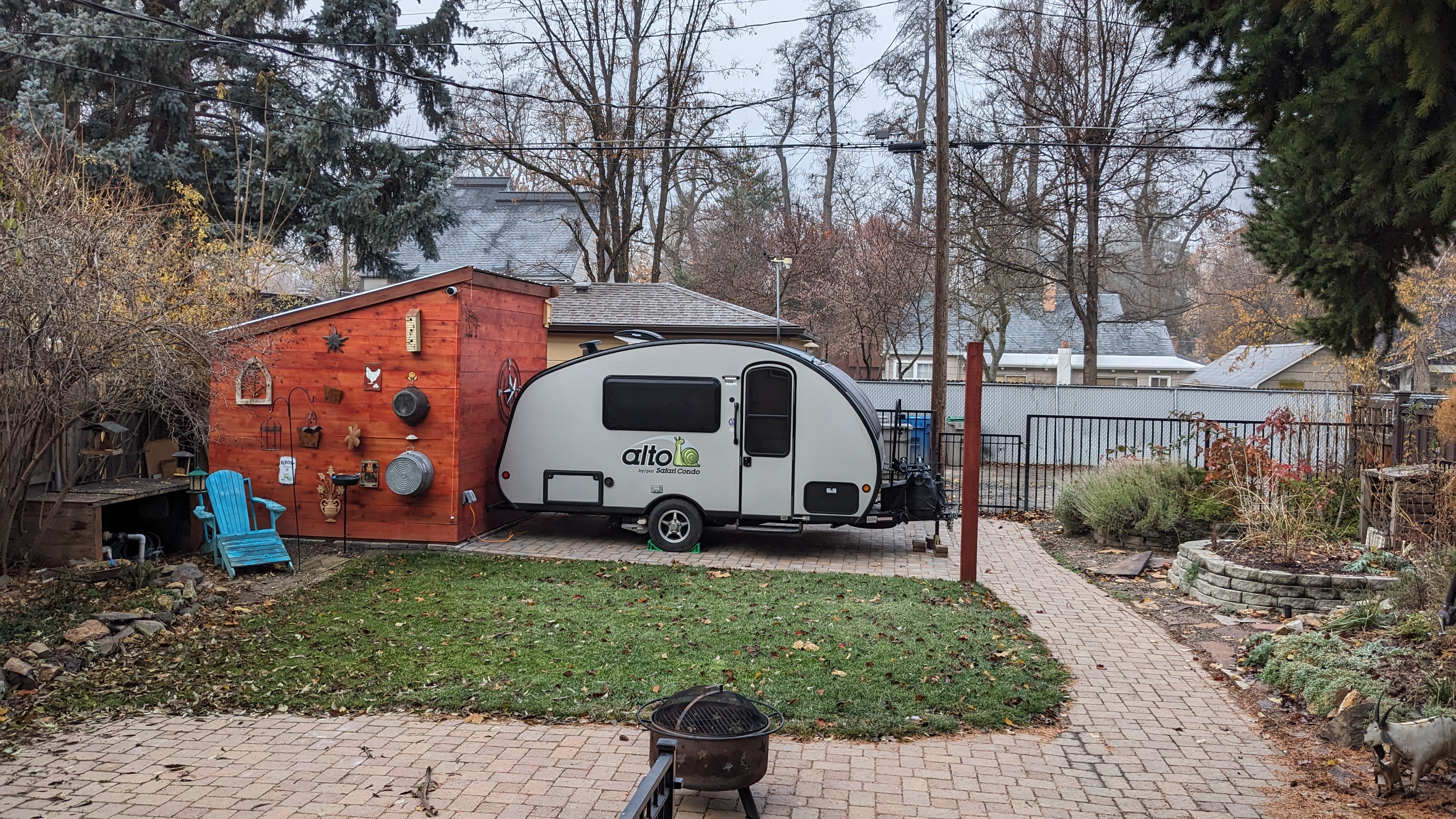
We recently acquired a 2023 Safari Condo Alto F1743 travel trailer. This is essentially the same trailer we rented a couple of years ago but with even more factory options. We pull it behind a 2023 Tesla Model Y Long Range EV. The installed options that impact the electrical system include
- 200 Ah lithium battery (two 100 Ah Volthium batteries)
- 220W rooftop solar (two 110W Merlin solar panels)
- Epever solar charge controller
- 2000W Xantrex inverter
- Truma caravan mover
- 4.3 cu ft NovaKool 12V compressor refrigerator
- Television w/ Furrion external antenna and wifi booster
- Additional AC and DC outlets
Had I opted to purchase the trailer new I wouldn’t have chosen the inverter option. It’s costly, heavy, and of limited practical use, especially with no microwave installed. But now that I have it I plan to keep it. It will be useful for charging e-trike batteries and powering a future single-burner induction stovetop or maybe an induction water kettle. And who knows, we may miss the microwave. It could also charge the EV, though with only 200 Ah of battery storage it can’t charge it much.
There are still three options missing: External solar, electronic sway control and a Tire Pressure Monitoring System (TPMS). In my effort to add these features I encountered some issues with the existing electrical design and decided to resolve them at the same time.
Much of what I’m doing here is based on prior work by pioneering Alto owners, helpfully documented on the Altoistes Facebook group. Thanks to all. Here’s the result of my effort: Alto F1743 Upgraded.
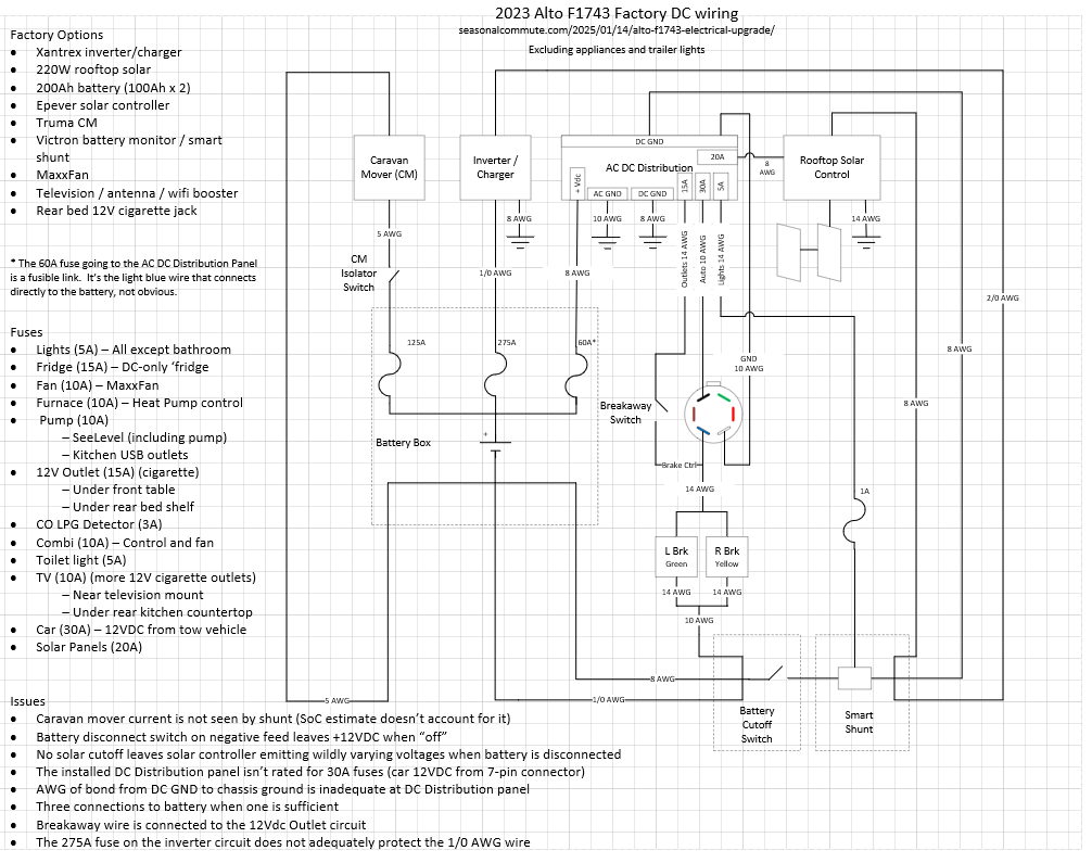
The Issues (in no particular order)
- The installed Victron Smart Shunt does not capture the current drawn by the Caravan Mover (CM) so it’s use is not accounted for in the State of Charge (SoC) measurement. I plan to use the CM often to avoid backing into tricky camp spots, optimize the position of the trailer in the spot, and save the EV battery for getting us back to civilization. Once settled in camp I’d like to know how much charge is left on the trailer batteries but the Victron will read too high in this scenario.
- The battery disconnect switch (big red handle) is on the negative side of the circuit, leaving some of the circuitry at 12VDC even when “off”. This doesn’t leave any of the components energized because the ground path has been disconnected but it does make it easy to find both 12VDC and ground when poking around, a safety concern.
- There is no solar disconnect switch, leaving the solar controller energized whenever the solar panels see light, even when the battery is disconnected. In addition to the safety concern, when the battery is disconnected the Epever solar controller emits wildly varying and out-of-spec voltages which can damage trailer electronics. The workaround is to pull the solar fuse before disconnecting the battery but this is a pain and can cause a spark, especially when reconnecting. And the solar controller remains needlessly and confusingly energized.
- At only 8 AWG, the wire connecting DC ground on the distribution panel to the trailer frame seems inadequate. In the event of a fault it should be able to handle the same current supplied on the positive side of the circuit. So 1/0 gauge (or really 2/0, read on..).
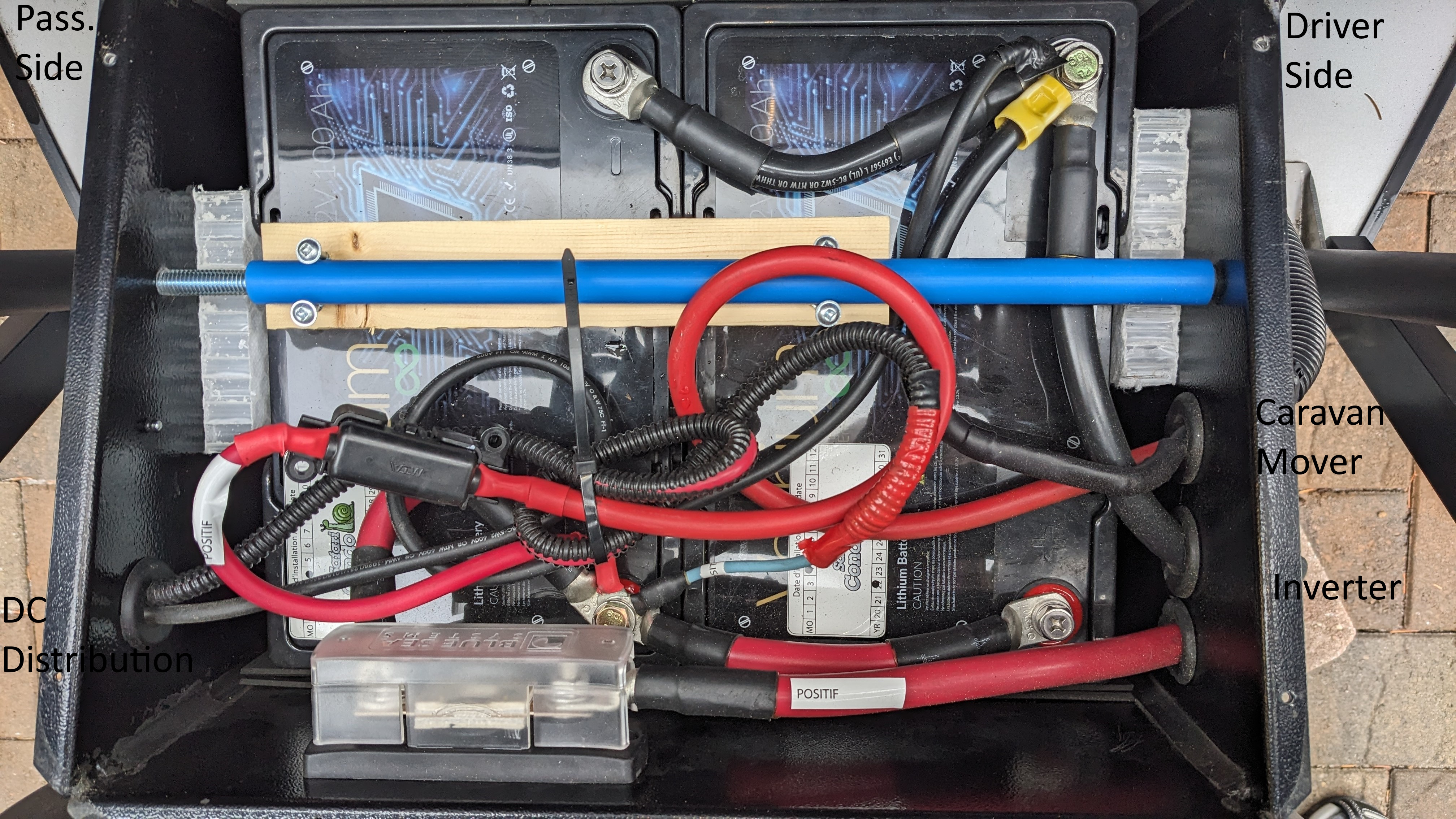
- It seems that SC adds options incrementally, which leads to overly complicated electrical wiring. For example the base configuration includes 8AWG wire between the battery and the DC distribution panel. When the inverter option is added, separate 1/0 wiring is added from battery to the inverter. When the CM option is added yet another set of 5 gauge wires are added. And as far as I can tell the CM wires are installed as configured in the Truma installation kit, without cutting them to an appropriate length. All this creates a jumbled mess inside the battery box and elsewhere. This can all be consolidated into one set of 2/0 wires.
- The wire supplying power to the breakaway switch is connected to the 12Vdc Outlet circuit. This is kind of gross, it means if I plug something massive into one of the 12V outlets and blow a fuse, my breakaway switch is (silently) inoperative. I can see why SC wired it this way– they were out of fuse slots in the distribution panel and the 15A fuse for the outlets is appropriate for protecting the 14 gauge wire for the breakaway switch. By adding a second fuse panel I don’t have this problem, better to give the breakaway switch its own circuit. I’ll include power for the TSC sway control on this circuit– these two circuits are related and less likely to interfere with each other.
It was pointed out to me that SC may have lumped Outlets and Breakaway into a single circuit for a different reason: as an indication that the circuit has blown. This makes some sense because there is no outward indication that the breakaway functionality is inoperative. The idea is that it will be obvious that the outlet is blown and the user will be incented to replace the fuse, incidentally fixing the breakaway functionality. On the other hand if the customer is starting the debug process by noticing the breakaway isn’t working, it requires reverse-engineering SC’s electrical design. I guess I’d be OK with this if they actually documented it. - The inverter circuit is connected with 1/0 AWG wire. Not only is this inadequate if the inverter is ever asked to deliver 2000W, the 275A fuse protecting the wire is too large, another safety concern. This is an even bigger issue with my plan to consolidate three battery connections (inverter, caravan mover, and DC distribution panel) into one.
- Many of the high-current DC cables connect to M8 (roughly 5/16″) posts with M10 (roughly 3/8″) connectors. This results in significant slop that can compromise the connection and should be avoided.
- Inline fuses. There’s one for shunt power buried somewhere in the rat’s nest of wires under the front skinny cushion and another for the CM in the jumble of wires inside the battery box. The problem with inline fuses is that it’s difficult to know they even exist, adding an unnecessary challenge to troubleshooting electrical problems. Bonus: power for the DC distribution panel is protected by a nearly invisible fusible link inside the battery box. All the disadvantages of an inline fuse, and more! There is still another fuse inside the battery box for the inverter circuit. This is a big fuse and would be appropriate and expected if it protected a single feed for all of the DC subsystems, but as-is it’s just another unexpected inline fuse.
Factory Wiring

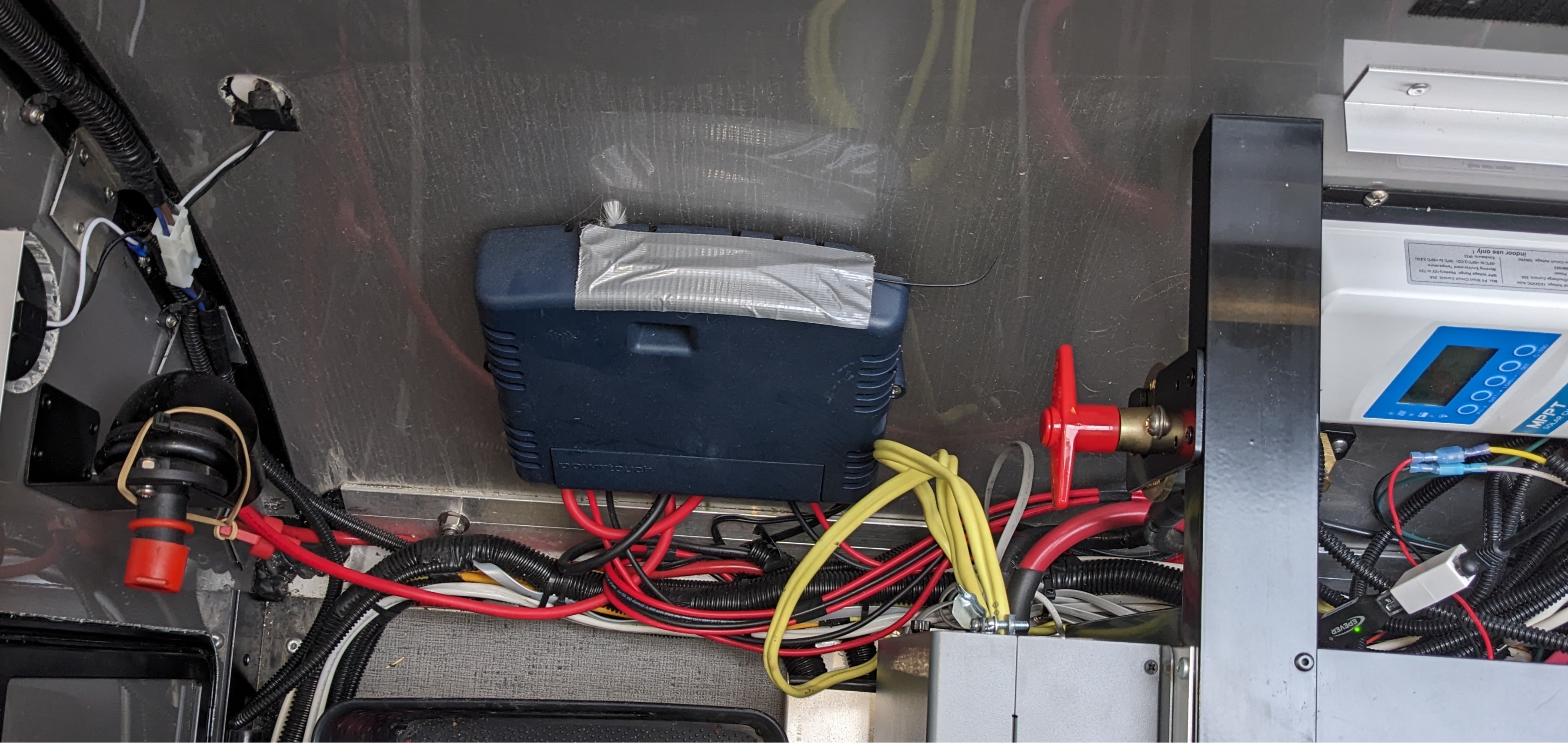
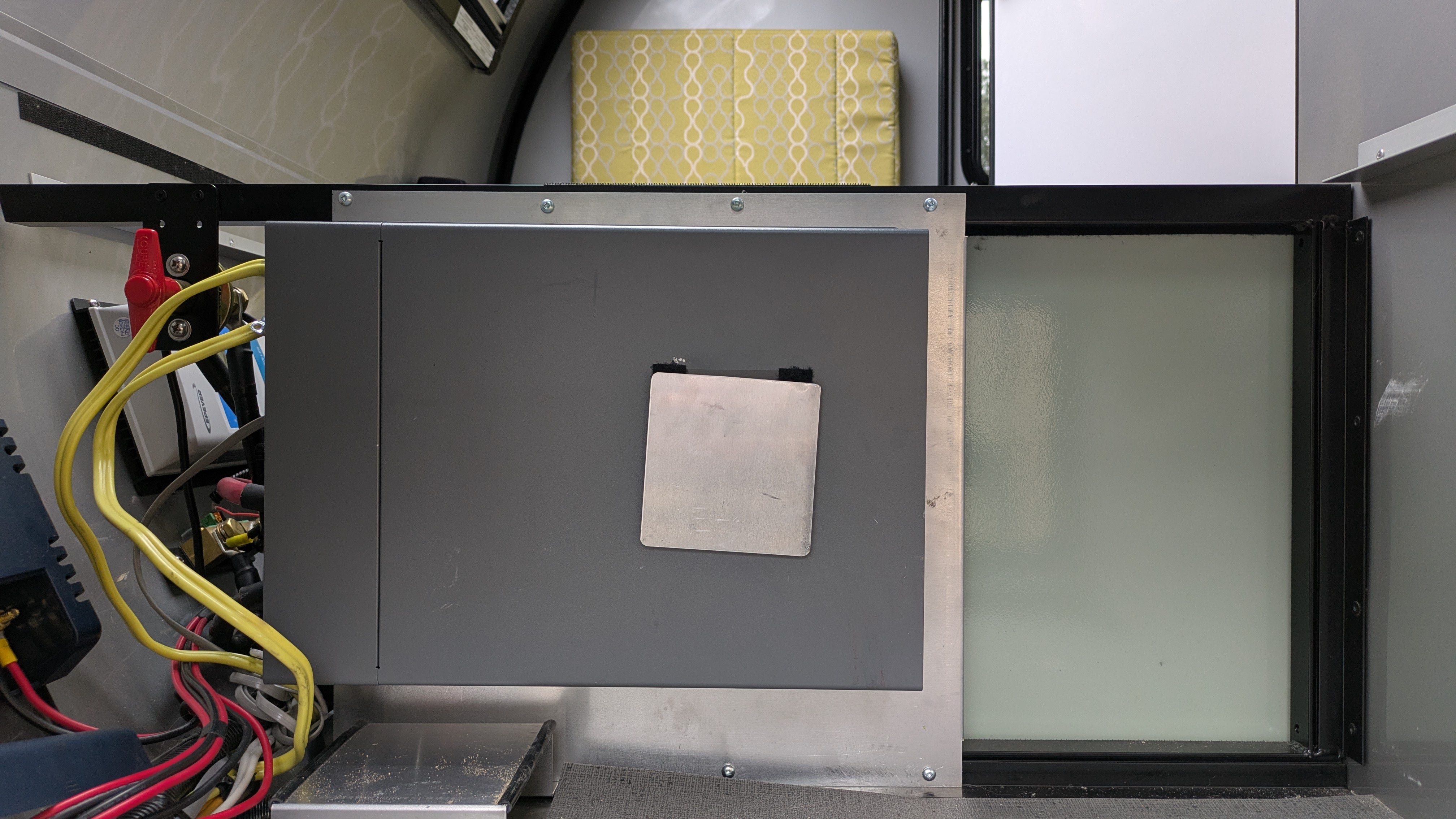
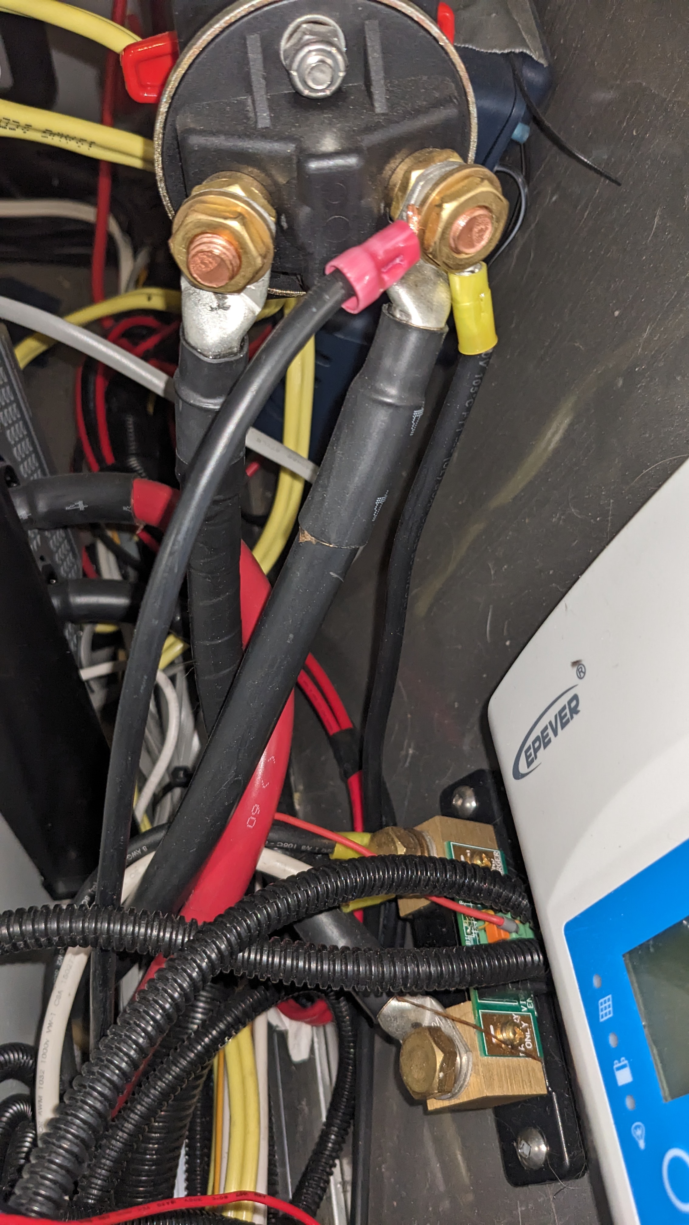
The picture below shows the back of the battery disconnect switch (big red handle), wired on the negative side of the circuit. The big cable on the left goes to the battery side of the shunt. The big cable on the right goes to the negative battery terminal, for the inverter circuit. The red crimped cable goes to the negative battery terminal, for the DC distribution panel. The yellow crimped cable eventually splits into two wires, one for each electric trailer brake.
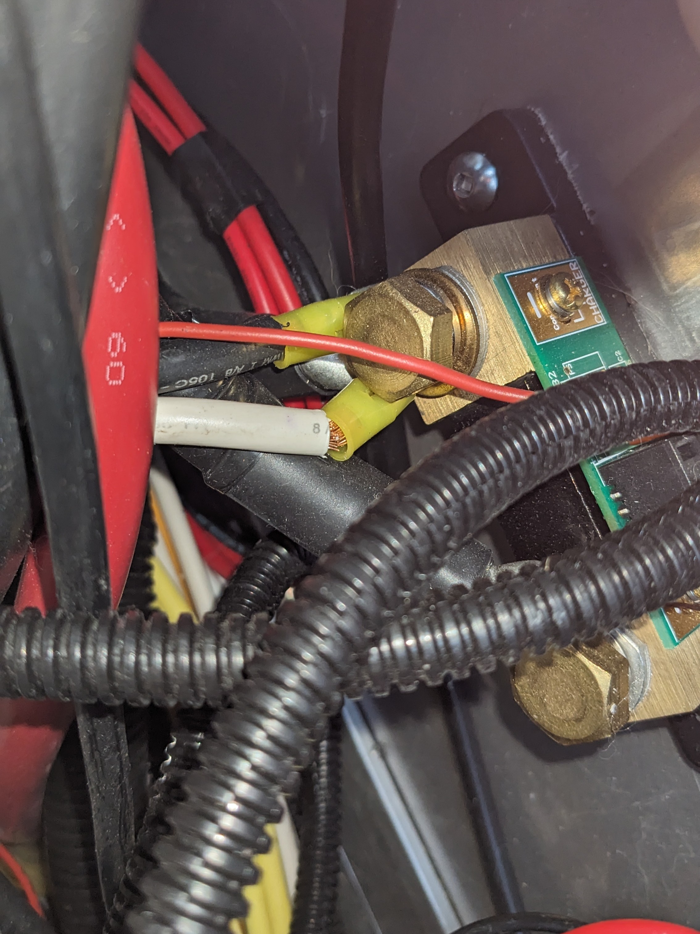
The following picture shows the Smart Shunt. The bottom terminal is the battery side and connects to the left terminal on the battery cutoff switch (see picture above). At the load side terminal on top there is a big cable (hidden) that connects to the inverter. The smaller black cable (visible) connects to the DC distribution panel. The white cable (with broken strands) connects to the solar controller. The small red wire is power for the shunt electronics.

External Inverter Outlet
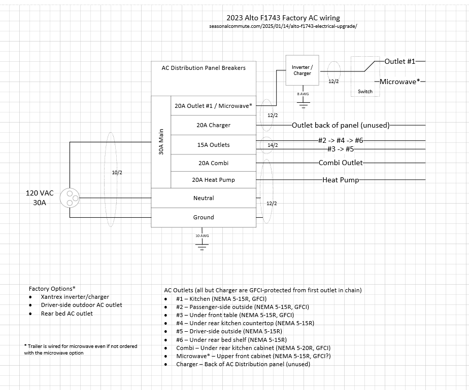
From the factory, Altos are configured so that the inverter can supply AC to only the microwave or a single kitchen outlet. As long as I’m lugging this inverter around it would be nice to be able to power something outside the trailer. The only something that currently comes to mind is the EV and for that the driver-side outlet would be best. This is pretty easily achieved by just moving the Romex supplying outlets #3 and #5 from the 15A Outlet breaker to the output of the inverter, with appropriate breakers for it and the existing microwave/outlet #1 circuit. And beefing up the Romex feeding the breakers from 12/2 to 10/2 AWG since it could now carry as much as 36A if both circuits are maxed out. With this change both the GFCI outlet under the front table and the downstream outlet on the driver-side trailer exterior will be able to be powered from the battery.
I know, charging an EV from 200Ah of battery is hardly worth the effort. I figure it would yield something south of 10 miles of additional range and leave the trailer batteries completely drained. But with 220W of rooftop solar, 500W of external solar, many days of a lot of sun, and a small animal sacrifice it could make sense in a pinch. Maybe more battery some day? Who knows. But I only have to do it once to claim my ride is solar-powered.
External Solar
When at camp we’ll do our best to park the trailer under shade. To compensate for the reduced solar production we’ll deploy a portable solar panel, yet to be purchased, probably in the 220-500W range. Since the panels produce higher voltage at less current than the 12V output of the controller, it’s more efficient to place the controller close to the battery rather than at the panels. More efficient because there will be less voltage drop over a potentially long run of wire between the panels and the battery. With 220W panels for both rooftop and external solar, I could get away with Victron 75/15 controllers for all practical purposes. But 100/20 gives me a little more headroom at a modest increase in size and cost. Replacing the Epever controller with Victron just about makes up for the second solar controller in terms of space. I also prefer Victron over Epever in general.
Sway Control
The trailer came with a Reese weight distribution hitch. I didn’t use it on the initial trip home from where we purchased the trailer in Michigan because the bottom portion was too close to the ground when connected to our tow vehicle, a 2023 Tesla Model Y Long Range. It could be made to work by lopping off the unused bottom portion of the hitch but I plan to remove it. WD hitches work by transferring weight from the rear axle of the TV to the front axle and trailer. This can indirectly help address trailer sway by improving traction on the TV front steering wheels. But WD hitches add stress to the TV frame, something many car manufacturers discourage, and don’t directly address trailer sway. With trailer GVWR less than half the weight of the tow vehicle and hitch weight less than 350 pounds, the benefits of WD are likely minimal and come at a high cost in terms of weight and complexity. Complexity in hitching/unhitching is a bigger deal with an EV since many chargers require dropping the trailer and we’ll be stopping more often than with an ICE TV. This is one of the reasons we chose one of the lightest trailers available, we plan to take advantage of it.
Some WD hitches (not mine) specifically address trailer sway but this adds even more weight and complexity. Electronic systems available from Tuson and Curt provide better sway control than mechanical systems with no cost in terms of weight or complexity. If the trailer is loaded properly, electronic sway control might be unnecessary with this setup but it’s essentially free insurance after the initial $.
I chose Tuson over Curt because it integrates more cleanly with the trailer. It also controls the brakes differentially instead of applying the same control to both brakes. Tuson makes a big deal out of this but I’m not convinced it makes a big enough difference to warrant the increased cost and install complexity.
Tire Pressure Monitoring System
Another in the category of cheap insurance. Every account of trailer tire blow-outs I’ve heard of involved expensive damage to the trailer wheel trim, etc. Behind an EV I’m not sure how long it would even take to notice a problem back there.
I considered several TPMS systems that put the sensor on the end of the wheel stem. They’re relatively inexpensive but don’t get high marks for reliability or battery life, though the batteries are at least replaceable. The weight of the sensor puts stress on the stem, the source of some of the reliability concerns. They can also complicate adding air to the tires.
The Tuson system is more expensive but uses automotive pressure/temperature sensors where the bulk of the sensor is inside the wheel. These should be as seamless and reliable as the sensors in the TV and last about as long (Tuson estimates 5 years). Probably longer since the trailer is used a lot less than the TV, which is also our daily driver when not travelling. However like the TV, the battery in the sensors can’t be replaced. Another benefit is that the Tuson repeater transmits trailer battery voltage in addition to tire pressure and temperature. This is useful for us since the TV doesn’t charge the trailer battery. We’ll be relying on solar to keep the 12V compressor ‘fridge running while on the road.
In addition to traditional automotive sensors that attach near the stem, Tuson now offers “ball” sensors. The same electronics packaged in a small plastic ball that weighs almost nothing. Pop the bead on the tire and drop the sensor inside where it rattles around until quickly pinned to the rim perimeter. Installation is easier though I probably won’t benefit because I’ll need a tire shop to install them anyway. But intriguing enough to give it a try.
It’s a little annoying that the smallest package Tuson appears to offer has four sensors. I only have two trailer wheels. But my brother has two more wheels on his trailer, thinking I’ll just give him the extra sensors, who knows how much battery life they’d have left after the originals die. All he’d have to purchase is the receiver initially, if he has communication problems he could then purchase the repeater. Tuson conveniently sells them separately and the net cost would be cheaper than what I paid initially.
Proposed Wiring
See the completed project here.
Acronyms
| SC | Safari Condo |
| EV | Electric Vehicle |
| SoC | State of Charge |
| ICE | Internal Combustion Engine |
| TV | Tow Vehicle |
| WD | Weight Distribution |
| CM | Caravan Mover |
| TPMS | Tire Pressure Monitoring System |
| AWG | Average Wire Gauge |
| GFCI | Ground Fault Circuit Interrupter |
| NEMA | National Electrical Manufacturers Association |
