Monthly Archives: July 2025

Dining Table Reinforcement

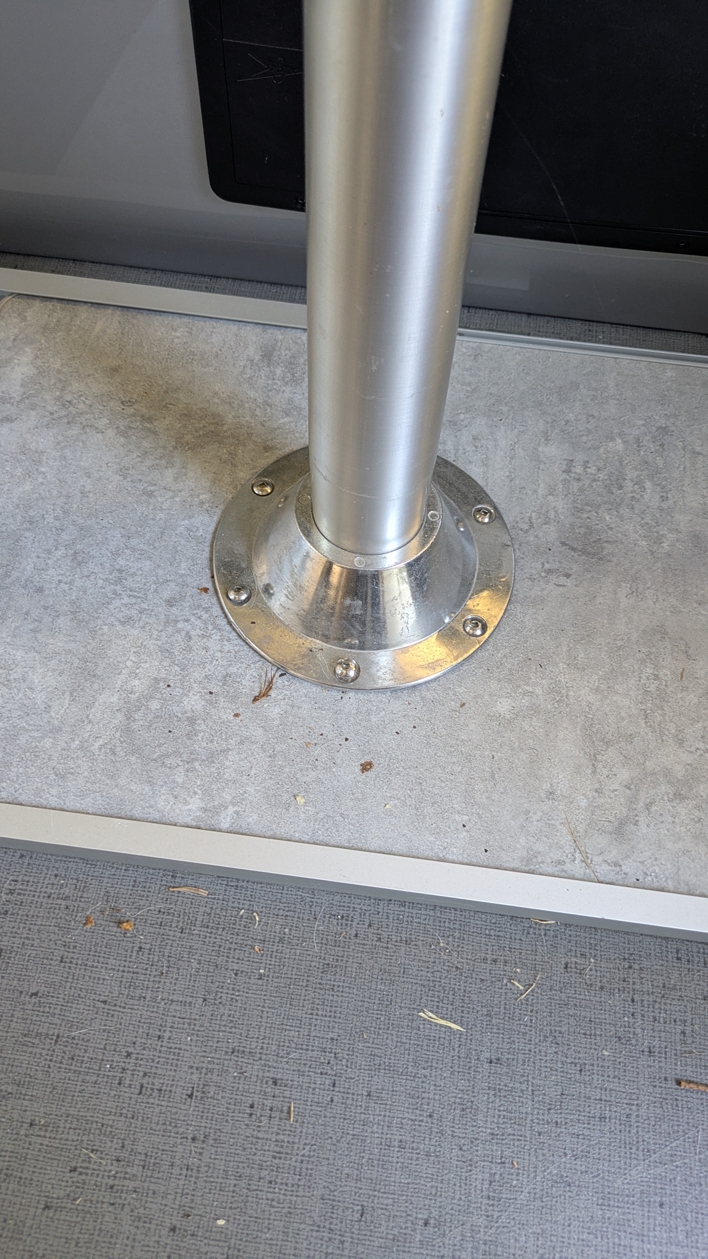
The stock dining table on my 2023 Safari Condo (SC) Alto F1743 was coming unmoored from the base. I tightened the screws a couple of times but they just loosened back up and a couple were stripped. I also discovered the pedestal flange was cracked at one of the screws.

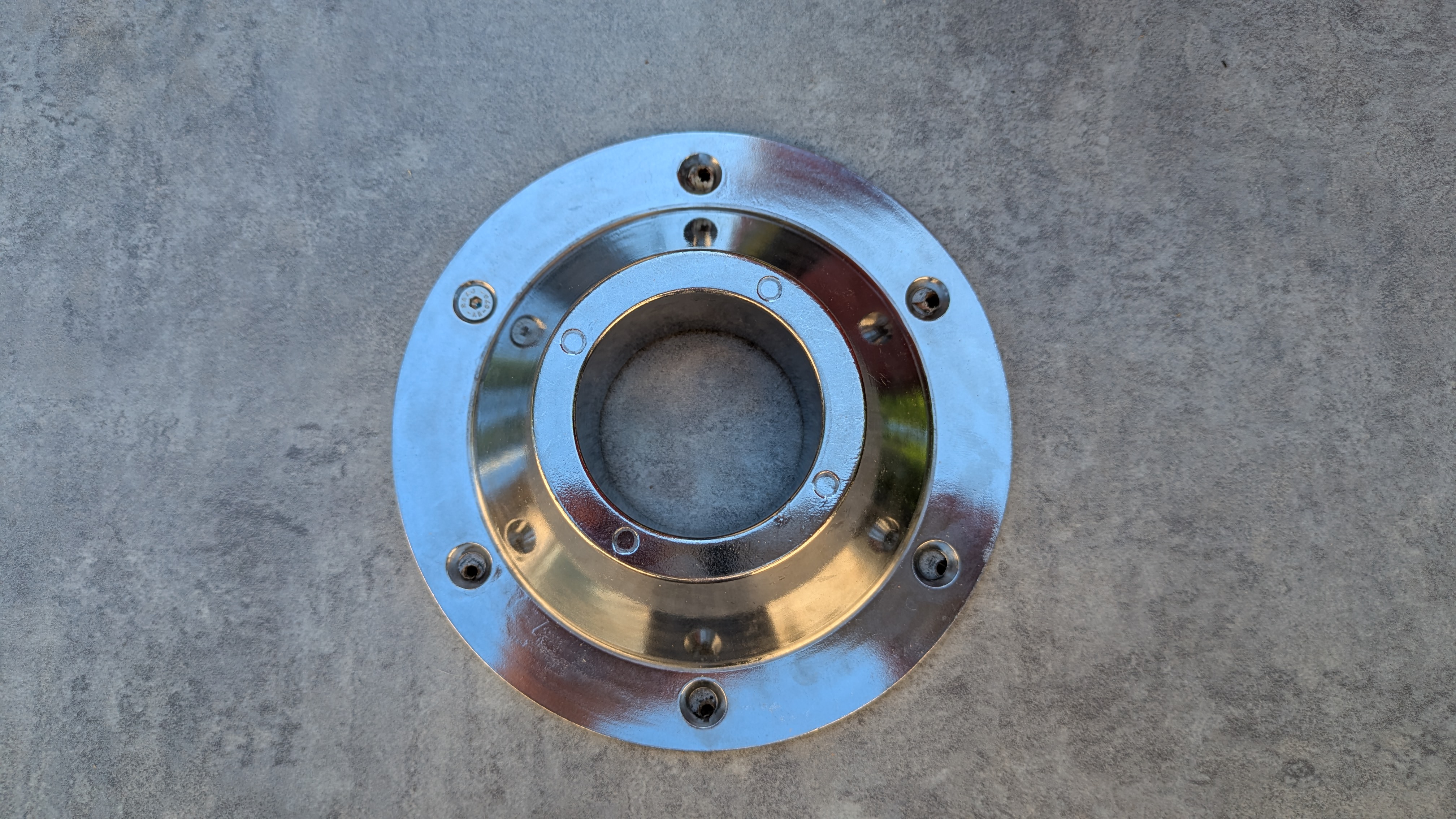
I did a quick search for this pedestal flange at Camping World hoping to find something local but didn’t. There were many possibilities on Amazon and this one seemed like a direct replacement. It does look identical– thin aluminum with chrome plating. And just as likely to crack, so good that it came with two pieces so I have a spare. But the hole pattern is slightly different as shown below. It isn’t that SC just drilled the holes slightly wrong– when the old and new parts are placed back-to-back the difference is obvious.

Slightly different hole pattern

I wasn’t sure what the material of this base board was until I began drilling into it. Some theories were an outer veneer around particle board or high density foam. But I think it’s actually plywood with a veneer. I’m not a fan of using wood screws to fasten the pedestal flange to any of these materials given how much force it sees when sliding that table back and forth or bouncing down the highway. My original thought was to use through-bolts but that would require counter-sinking on the bottom to recess the bolt head so the base board will still slide along the floor.

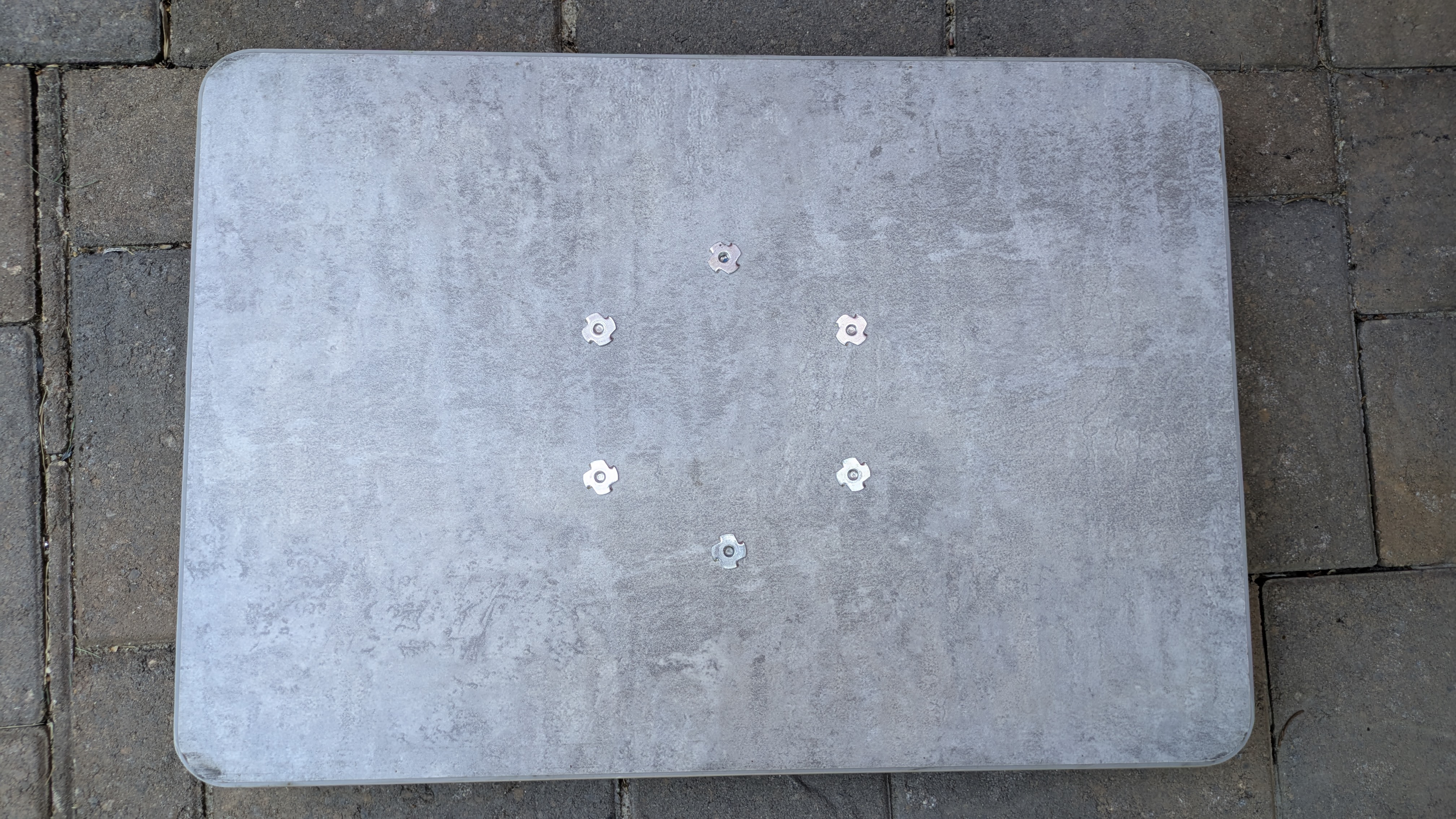
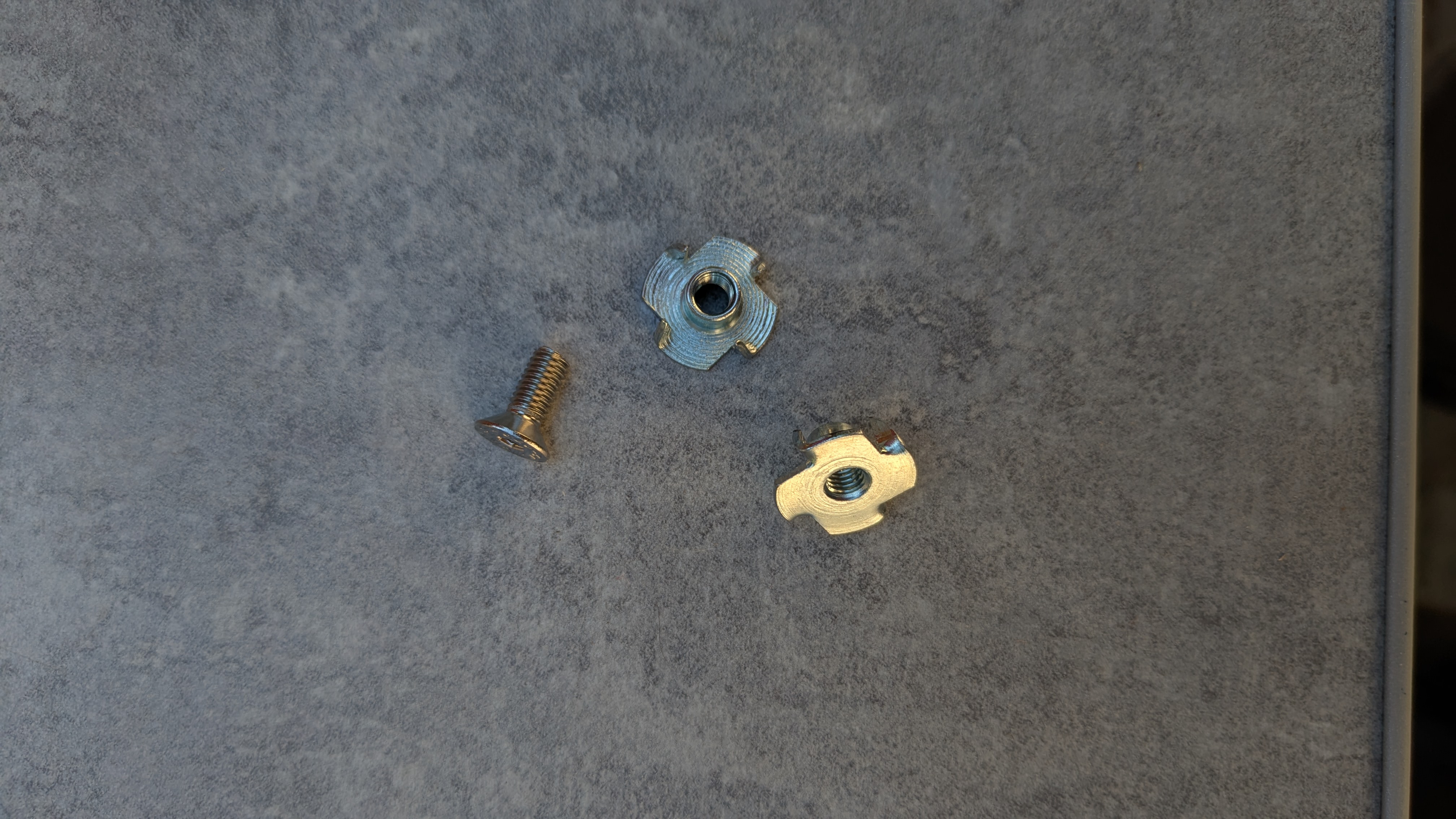
A helpful Altoiste recommended using T nuts. Brilliant. I wasn’t sure if they would recess enough to allow the base board to still slide but gave it a try. They work beautifully. The aluminum bracket on which the base slides is slightly thicker than the exposed edge of the T nut, so it still slides.

T nuts protruding on the bottom

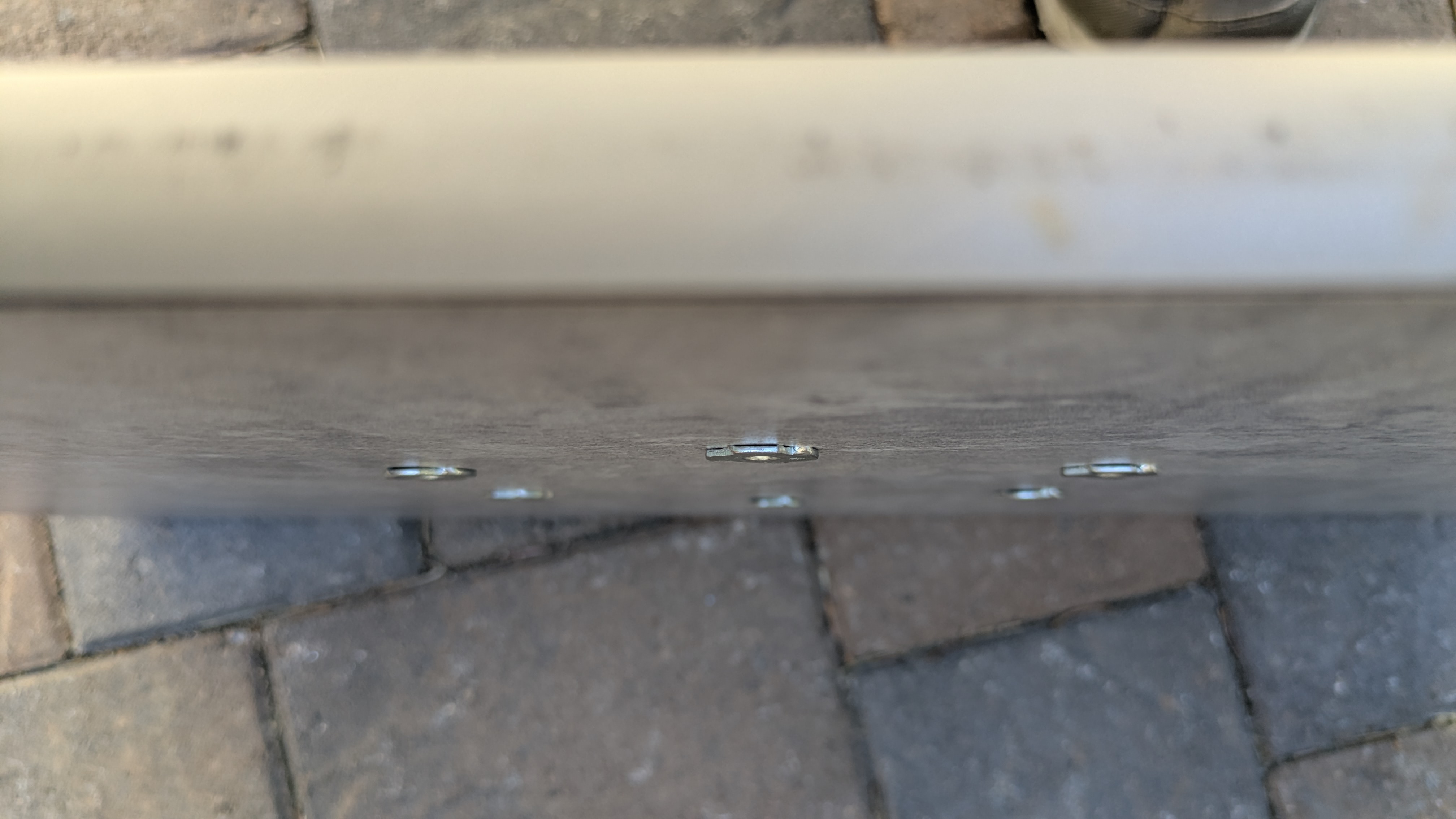
I used M5 T nuts and M5-0.8 16mm stainless steel flat head socket cap machine screws. The holes in the pedestal flange have a counter-sink taper. I think the taper in the screw head better matches the pedestal flange than the round-head screws with no taper that SC used and may be less likely to crack it. A 16mm screw length uses all of the threads of the T nut without protruding past the edge. To install the T nuts I used a long M5 bolt through a piece of scrap aluminum and tightened the nut until it was pulled tight against the base board. Note the picture below shows a 12mm screw length, before I switched to 16mm.

Machine screw and T nuts

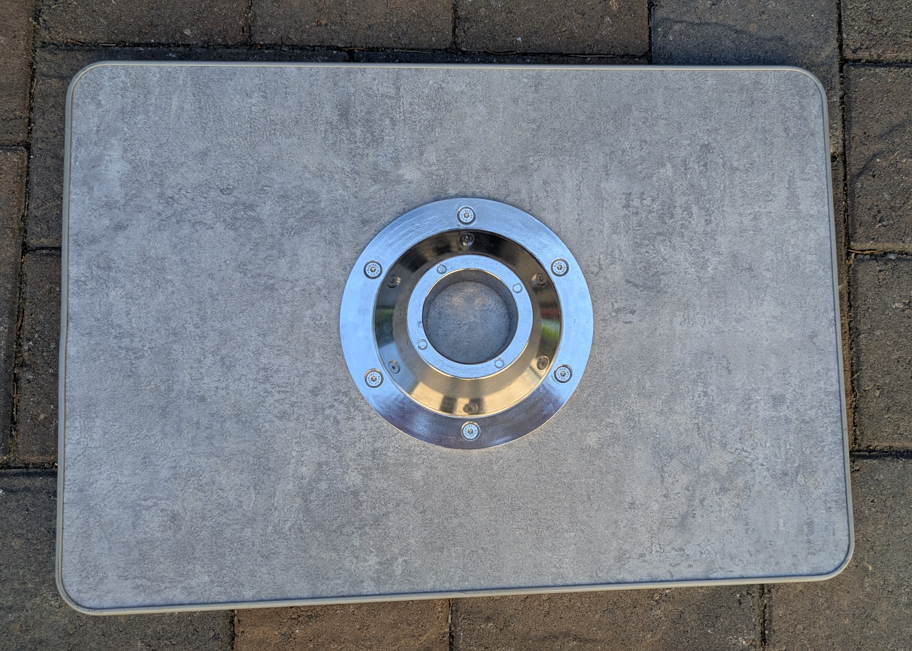
The trim around the edges of the base board is offset so the original bottom was flush with the board and the top had some trim overhang. I figured this must have been intentional so mounted the pedestal flange on the same side. I now think it probably doesn’t matter. Because the hole pattern was slightly off I couldn’t just drill out the the existing holes so I used the new pedestal flange as a template. I drilled out one existing hole and secured the flange with screw and T nut, then drilled the remaining holes through the flange. I thought I might destroy the flange in the process so was happy to have a spare, but it survived. It might have been a better idea to simply rotate the pedestal flange and drill entirely new holes, but this worked.

In the final assembly I added blue thread locker to the machine screws. I also considered adding adhesive between the base board and pedestal flange. SC had used some sort of silicon adhesive but I don’t think it really adhered– I had no trouble separating the two parts. I decided against adhesive. I don’t think the combination of T nuts and machine screws with thread locker will be coming loose any time soon and I don’t want to make things harder if I ever need to revisit this. I think the weak point now is the pedestal flange itself.

When I initially disassembled the table I had a hard time separating the table leg from the bottom pedestal flange. I ended up unscrewing the flange and banging it off with a rubber mallet. I don’t know if it will help but I added a tiny bit of ant-seize compound to both the bottom and top of the table leg. We never convert the table into a bed so not a big deal for us if it seizes again.

For now the table is as solid as ever.

Flippin’ Shades

Today I flipped the shades on the Big Front Window (BFW) so that the blackout shade is on bottom and the bug screen is on top. I did this to improve airflow between the shades and the window in an attempt to avoid excessive heat buildup that could warp the window, apparently a thing with the BFW. The idea is to set the shades for 80% blackout on bottom and 20% bug screen on top and use convection (hot air rises) to vent heat buildup out the bug screen on top, pulling in cooler air at the bottom to replace it (crack open the BFW). Then aid the process by pulling out the hot air with the trailer’s roof fan. This helps keep the interior of the trailer cooler without cooking the window in extreme conditions. The orientation has the added advantages of somewhat increased privacy when partially deploying the blackout shade and putting the heavier blackout shade on the bottom where the wall is more vertical, reducing the tendency for the shade to sag.

Flipped, in convection mode

All of the shades in earlier Altos were oriented this way but sometime before my 2023 F1743 was built, Safari Condo (SC) began flipping them on all of their trailers. SC confirmed that Horrex is the manufacturer of my shades. The Horrex manual clearly states that the blackout shade should be on the bottom. SC told me the orientation is personal preference and that they flipped them for convenience. That doesn’t make a lot of sense to me considering the guidance from the manufacturer and the considerations listed above, but OK. Easy enough to flip them back.

And it was pretty easy. I was initially unsure whether the curvature in the frame is symmetrical but it clearly is. This means I could flip the entire assembly, frame and all, vs. swapping the cartridges that hold the blinds. It took me about an hour to do this job solo. A second person might have helped or more likely would have just been in the way. Judicious placement of seat cushions and pillows doubled for a second set of hands. Here are the steps:

  1. Remove the front table
  2. Pop off the four plastic covers at each corner of the frame by pulling them from behind
  3. Prop the bottom of the frame with cushions and pillows to keep it from flopping down when screws are removed. The top of the frame is held in place by two brackets so it stays put without the screws.
  4. Remove the two sheet metal screws at each corner that secure the frame to the wall of the trailer.
  5. Carefully slide the whole frame up slightly to detach the top frame from the brackets. The clearance between the frame and the light switch assembly is tight, I had to “bend” the switch assembly slightly to free the frame. There is enough natural play in that assembly, nothing was bent permanently.
  6. Carefully rotate the whole blind assembly 180 degrees. The frame is fairly solid when detached from the wall but can’t withstand too much sideways force.
  7. Hang the top of the frame on the brackets, again “bending” the light assembly slightly. Prop up the bottom of the frame with cushions and pillows to hold it to the wall of the trailer.
  8. Re-attach the two sheet metal screws at each corner. As with every other sheet metal screw in this trailer, be careful to avoid stripping it while tightening. So.many.sheet.metal.screws :(.
  9. Replace the plastic covers at each corner. The trick is to slide the pointy part of the cover over the inner corner of the frame first, then push it on the rest of the way from the outer part of the frame.
  10. Reverse the plastic clip that joins the two shades
  11. Behold the now upside-down and out-of-sight warning label
Two sheet metal screws at each corner
Tight clearance
Prop bottom with cushions and pillows
Removed, ready to rotate
Bracket, one of two
Brackets

If I had stripped one of the sheet metal screws in this process I would have replaced them all with rivet nuts and stainless steel machine screws. If I had the rivet nuts on hand I would have done this proactively, but I was impatient.

Rather than “crack open” the window using the built-in detents on the left and right latches, it has been suggested more airflow is needed, maybe a 1/2″ to 3/4″ gap. It’s difficult to measure but using the detents, the gap between window and seal seems slightly less than 1/2″. A fellow Altoiste pioneered some blocks that will hold the window out further. These would be simple to create and could potentially hold the window more securely: Three attachment points instead of two, at the bottom of the window instead of the sides, and more difficult to break in from the outside. Here’s a post showing his design https://www.facebook.com/groups/Altoistes/permalink/1204161736285064. And another where STL files were uploaded that can be used to 3D print the spacer blocks. https://www.facebook.com/groups/Altoistes/permalink/24523360507271858

Now I need to decide if I want to flip the remaining windows. My biggest concern was the BFW because I sometimes close the blinds while parked at home. I generally don’t close the other blinds and I don’t imagine the smaller windows are as susceptible to warping, but the same convection mechanism would apply. I’m not as concerned about the privacy aspect. I’ll probably flip them eventually.

I’ve read about concerns with flipping the kitchen window because of the tight clearance with the overhead shelf. Based on this experience, I don’t think it would be an issue, at least for my F1743. The frame doesn’t have to slide up much to detach from the brackets, it looks to me like there is enough clearance. And I would imagine the blinds went in after the shelf when the trailer was constructed.

Thanks to this post for the procedure and discussion about the merits of convection for the BFW: https://www.facebook.com/groups/AltoOwners/permalink/1746414862418213