The project is complete. It went pretty close to plan, details below.
Electrical Redesign
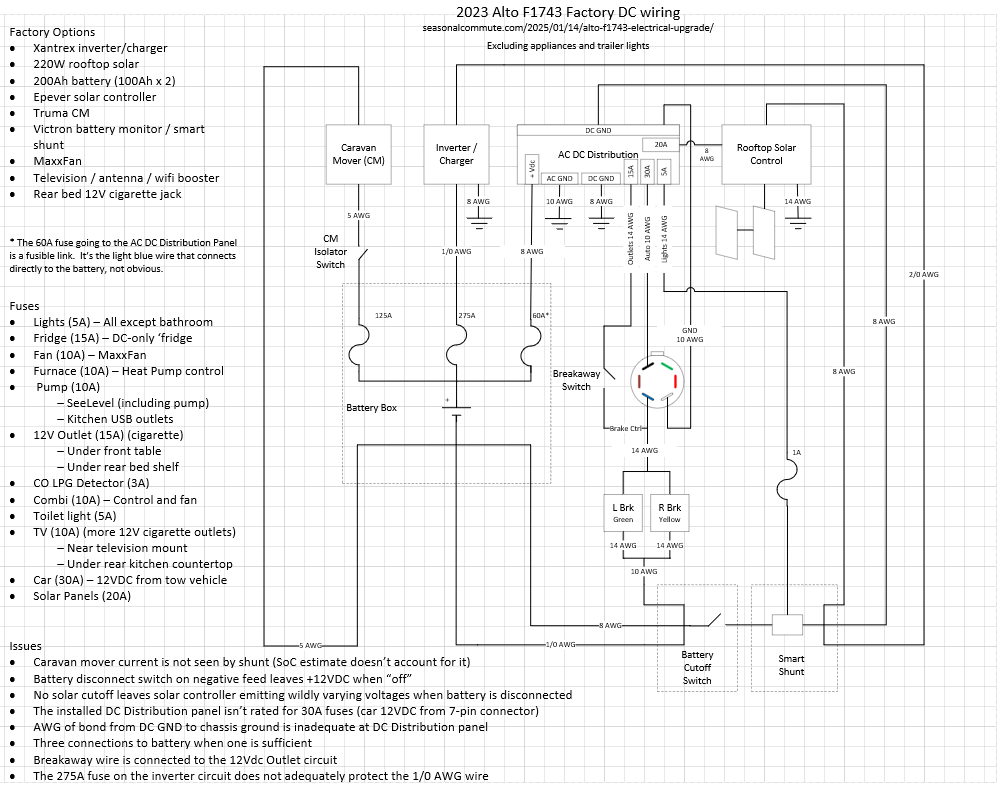
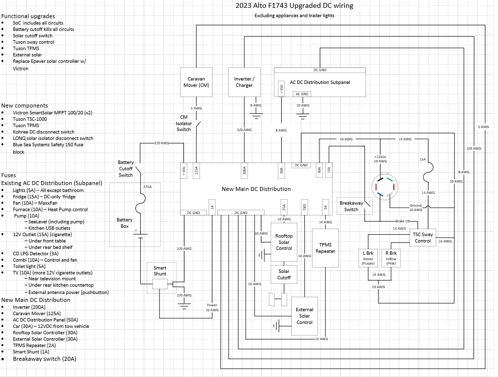
My original motivation for the electrical redesign was to include the caravan mover in the Victron battery monitor. Once I dug into it I corrected a number of additional issues, including
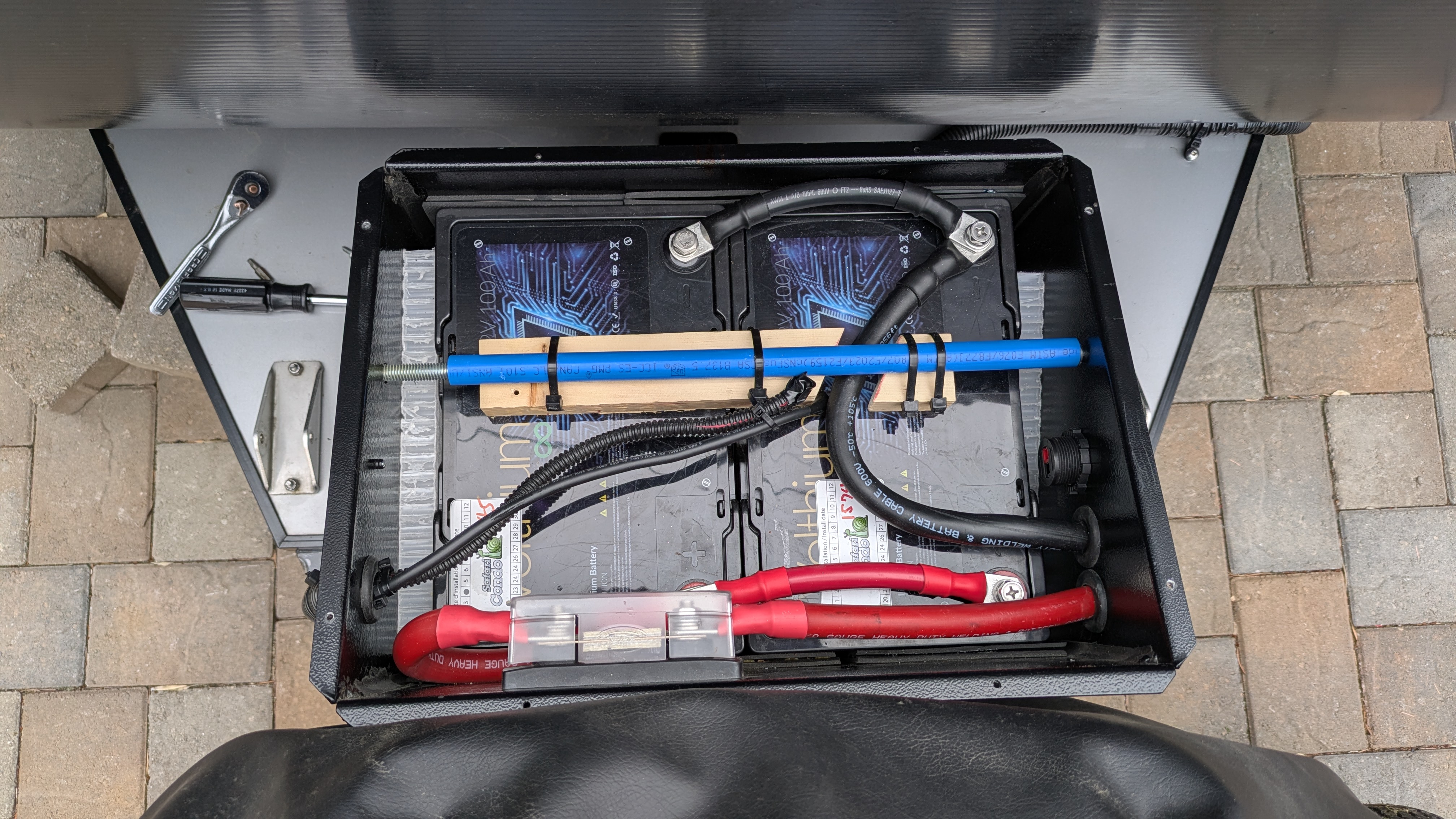
- Moved the battery cutoff from the negative to the positive side of the circuit for better isolation / safety.
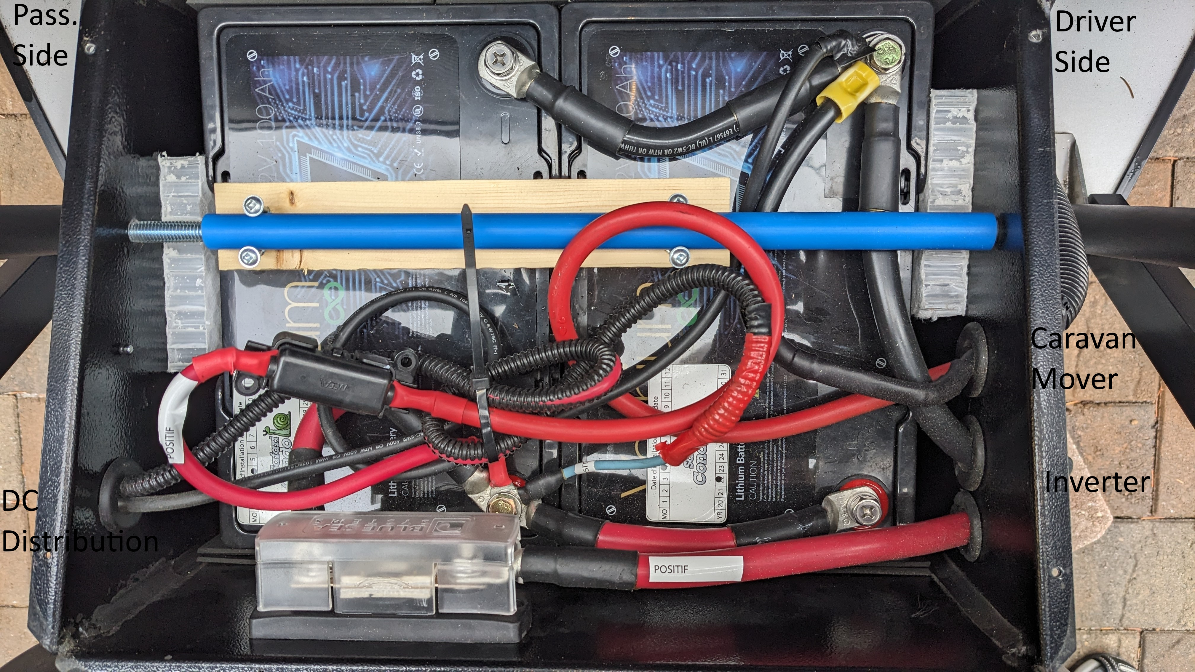
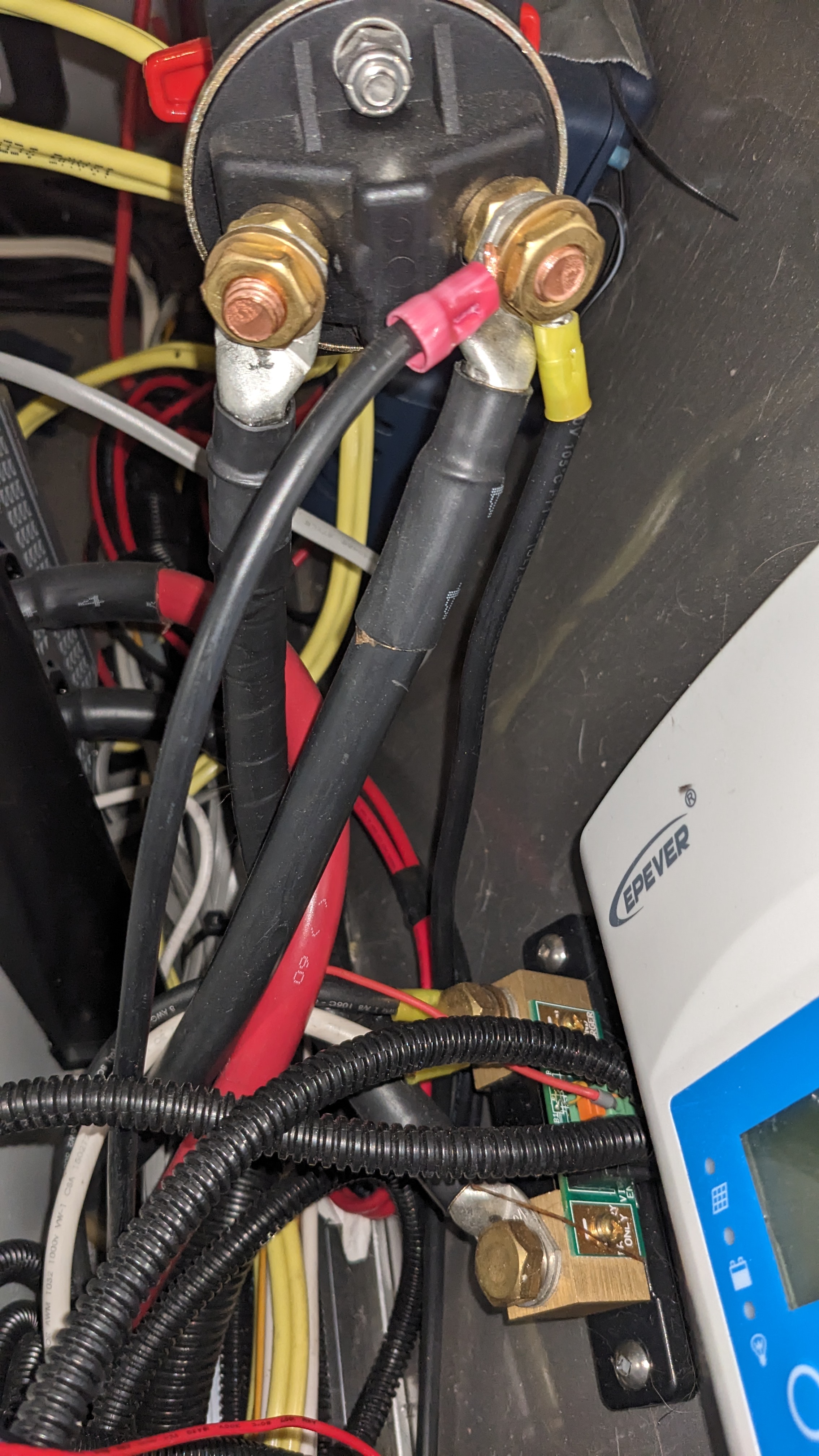
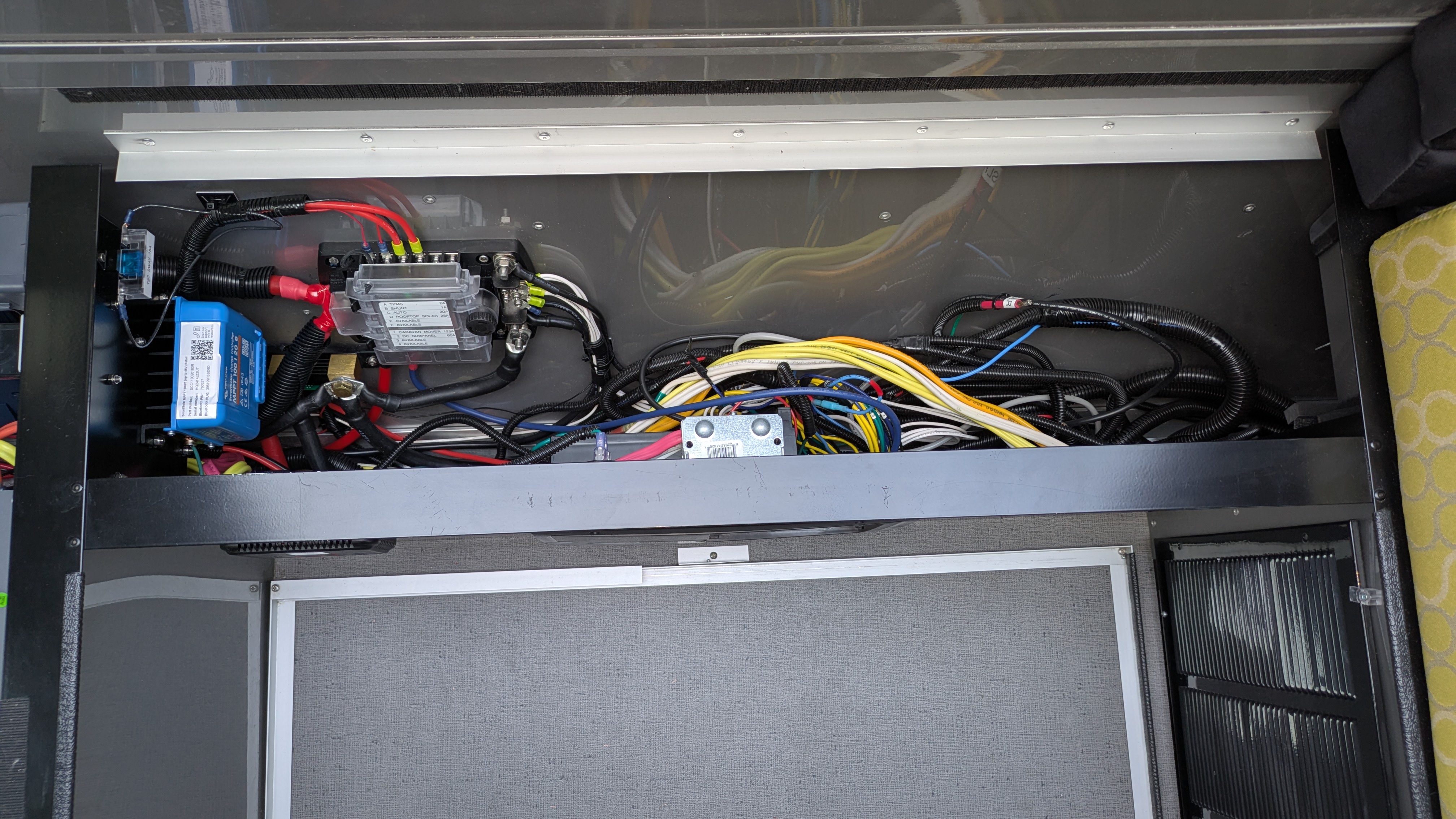
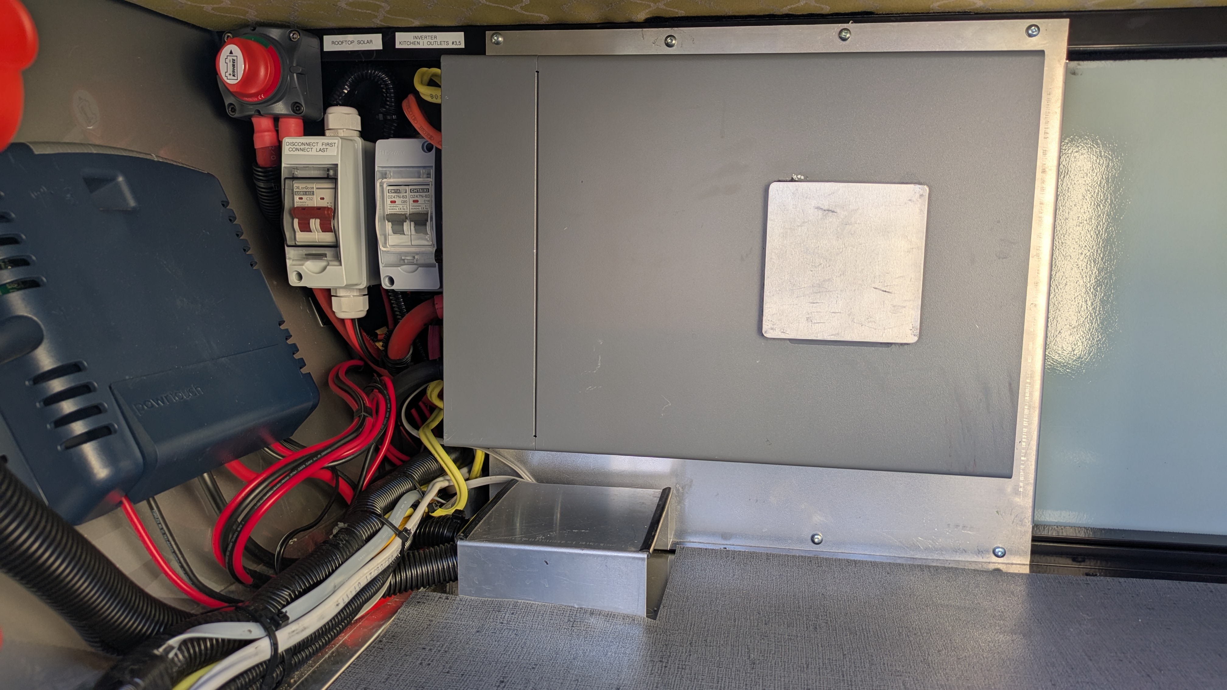
- Reduced wiring to the battery from three circuits to one. In doing so, upgraded the inverter wiring from 1/0 to 2/0 gauge wire to match the 275A fuse protecting it and made branch circuits out of the CM and original DC distribution panel, relegating the latter to a subpanel. Added the Blue Sea Systems DC distribution panel to manage all of the charging loads (inverter/charger, auto, and solar) as well as the new branch circuits. I decided to pull inverter power off of the main positive terminal of the Blue Sea panel rather than from one of panel fuses and rely on the 275A breaker in the battery box for protection. The stud housing isn’t really designed to handle two 2/0 connectors, I had to grind off some of the cover for it to seat properly in this area.
- Added a CNLonQcom isolator switch for the rooftop solar for better isolation / safety and easier winterization. The switch comes with the connectors installed on the wires but you don’t need them, they would just take up a lot of space for nothing more than another potential failure point. I removed the connectors from both ends (4 total). One set of leads was long enough to reach the Victron solar controller so I connected them directly. I butt-spliced the other set to the solar leads coming from the roof with 8 gauge waterproof crimp-style butt splices. Waterproof is overkill inside the trailer but it’s what I had.
- Increased the DC ground bond wire to 2/0 gauge to accommodate the current that the system can supply.
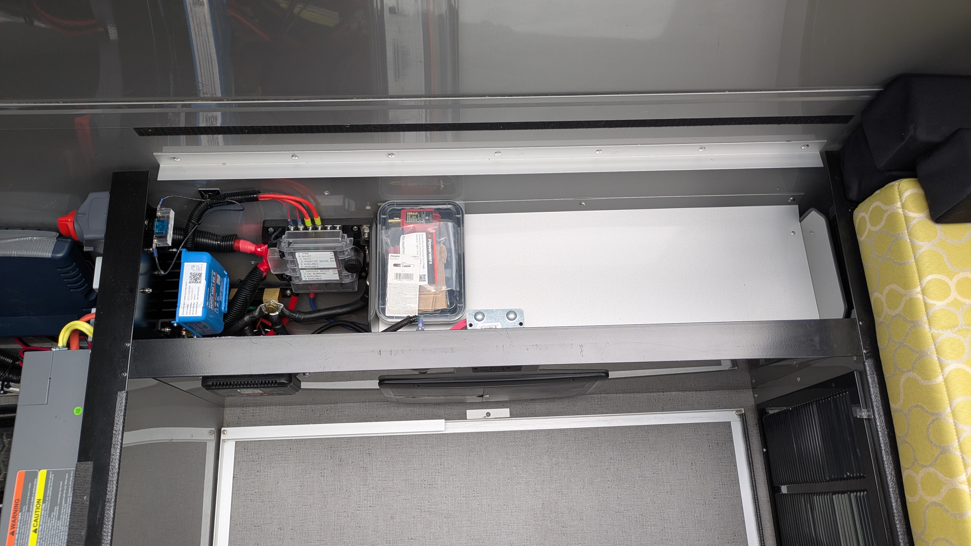
- Moved the breakaway circuit to its own fuse for reliability and to aid in troubleshooting. Also moved power for the Victron shunt to its own fuse. These changes were made possible by the addition of the Blue Sea Systems fuse panel.
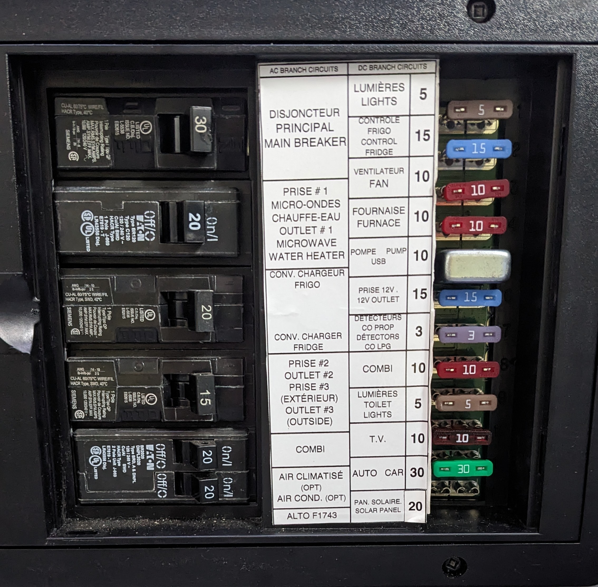
It was pointed out to me that SC may have lumped Outlets and Breakaway into a single circuit not because they ran out of circuits in the distribution panel but as an indication that the circuit has blown. This makes some sense because there is no outward indication that the breakaway functionality is inoperative. The idea is that it will be obvious that the outlet is blown and the user will be incented to replace the fuse, incidentally fixing the breakaway functionality. On the other hand if the customer is starting the debug process by noticing the breakaway isn’t working, it requires reverse-engineering SC’s electrical design. I guess I’d be OK with this if they actually documented it. - Got rid of a surprising number of unnecessary splices, particularly in the CM circuit.
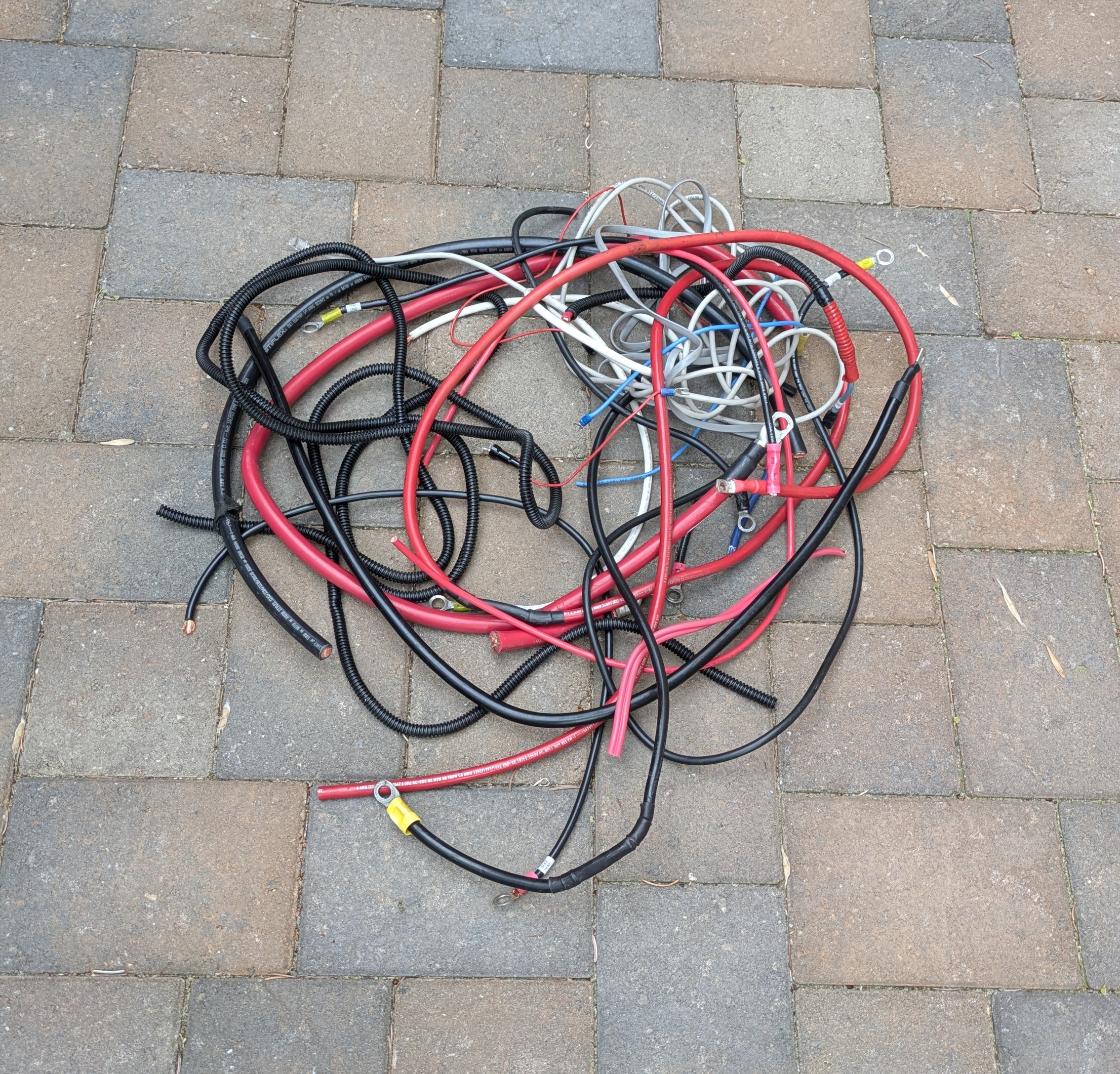
- And an astonishing amount of unnecessary wire. The most egregious example was over 20 feet of bundled telephone cord, half of which was inexplicably covered in plastic wire loom, eliminated with two simple RJ11 crimps. A service loop is one thing but this was pretty nuts. All told I removed nearly 4 pounds of wire and there are still plenty of opportunities to remove more.
- Replaced connectors to match the studs to which they connect. Many of the original connectors were oversized (3/8″ terminal on a 5/16″ post).
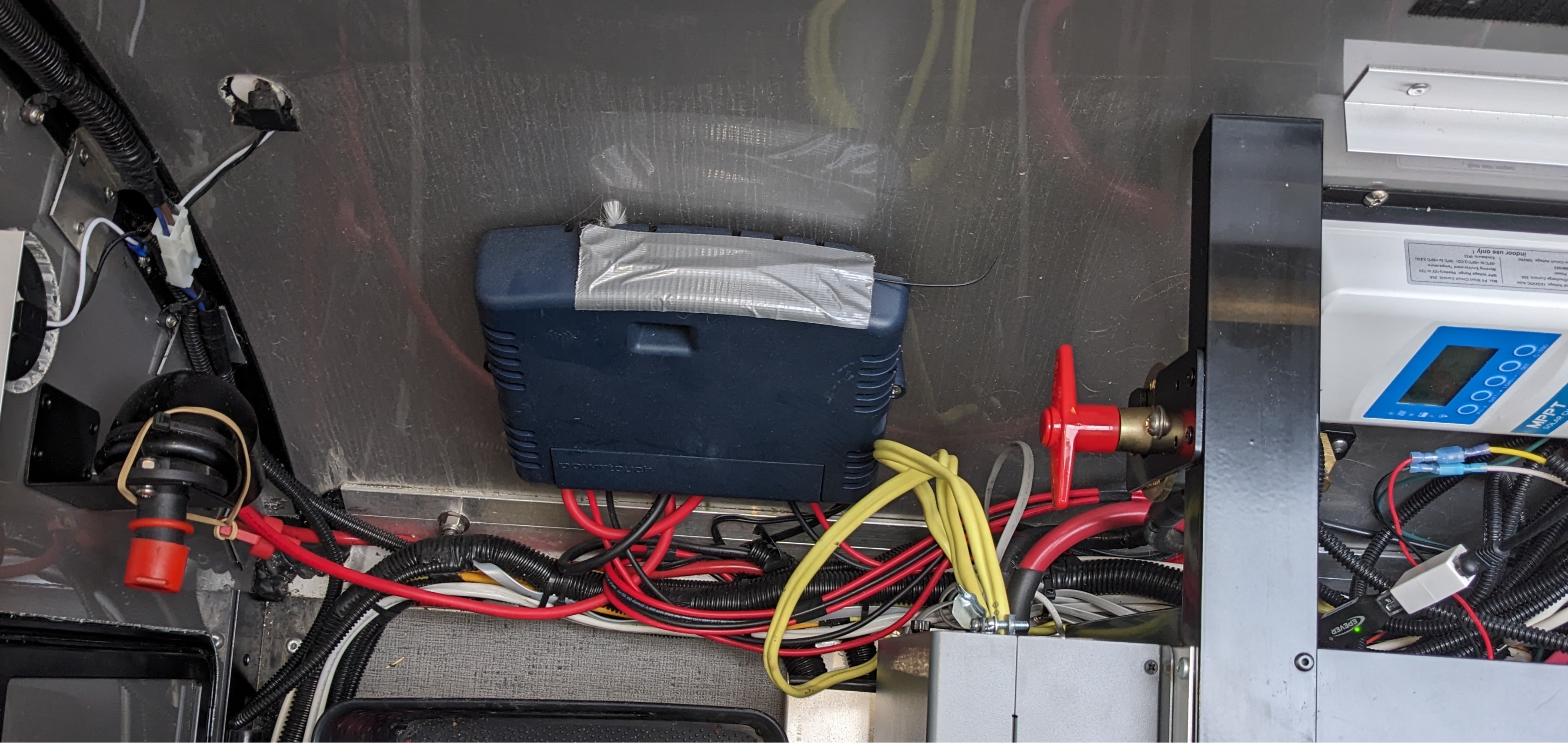
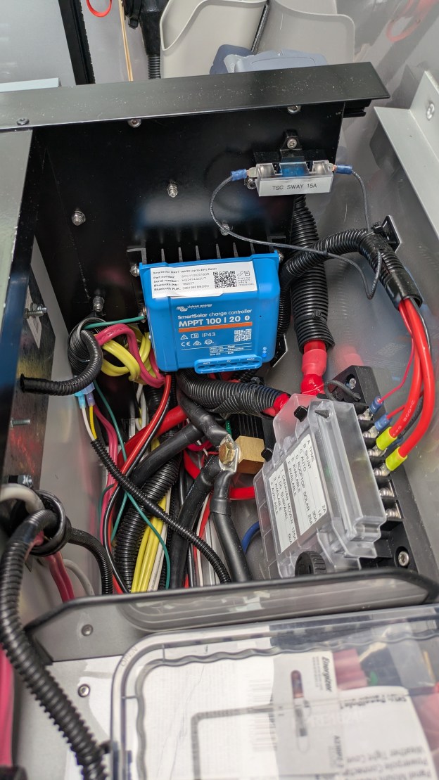
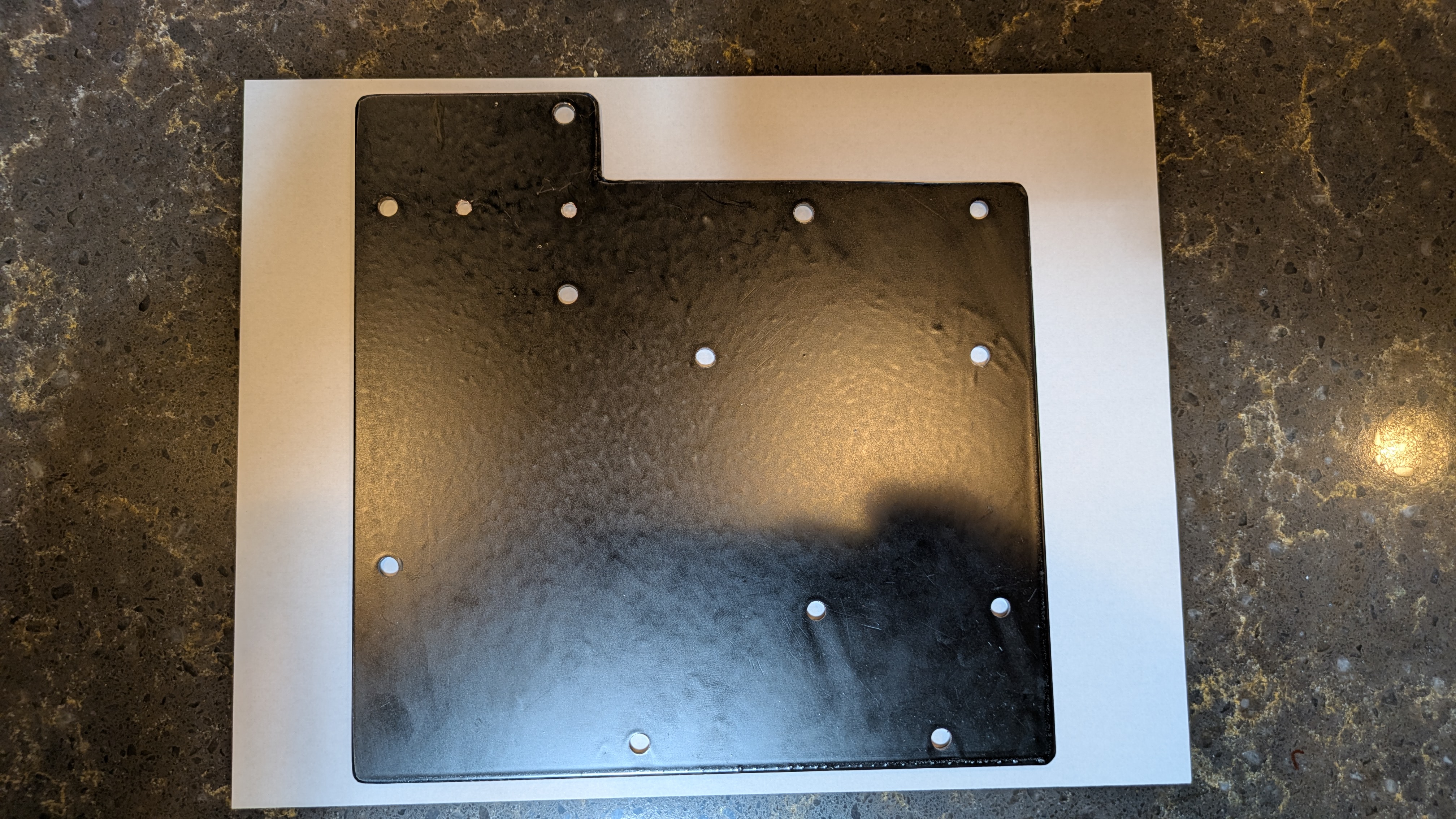
- Added a roughly 8″x8″x1/8″ aluminum plate onto which I mounted the rooftop solar controller, battery cutoff switch, solar cutoff switch, inline fuse for TSC, and 2-circuit AC breaker box.
The Blue Sea Systems fuse panel, shunt, shelf, and some of the aluminum plate were mounted using M5 rivet nuts. I flipped the shunt 180 degrees to achieve slightly better cable routing.
Functional Changes
In addition to the above improvements I added the following new functionality.
Tuson Sway Control (TSC)
I first had to choose a location for mounting the main unit. The Tuson installation video doesn’t really address a trailer like the Alto but there are several obvious choices, each with advantages and disadvantages.
| Location | Pros | Cons |
| Under belly of trailer | * SC’s location (I think) | * Very exposed * Mounting most difficult * Wiring most difficult |
| Under front skinny cushion | * Easiest wiring * Completely protected | * Mounting more difficult * Uses valuable space |
| Behind battery box | * Easiest mounting * Mostly protected * Uses otherwise wasted space * Not mounting to trailer skin | * Must waterproof connections |
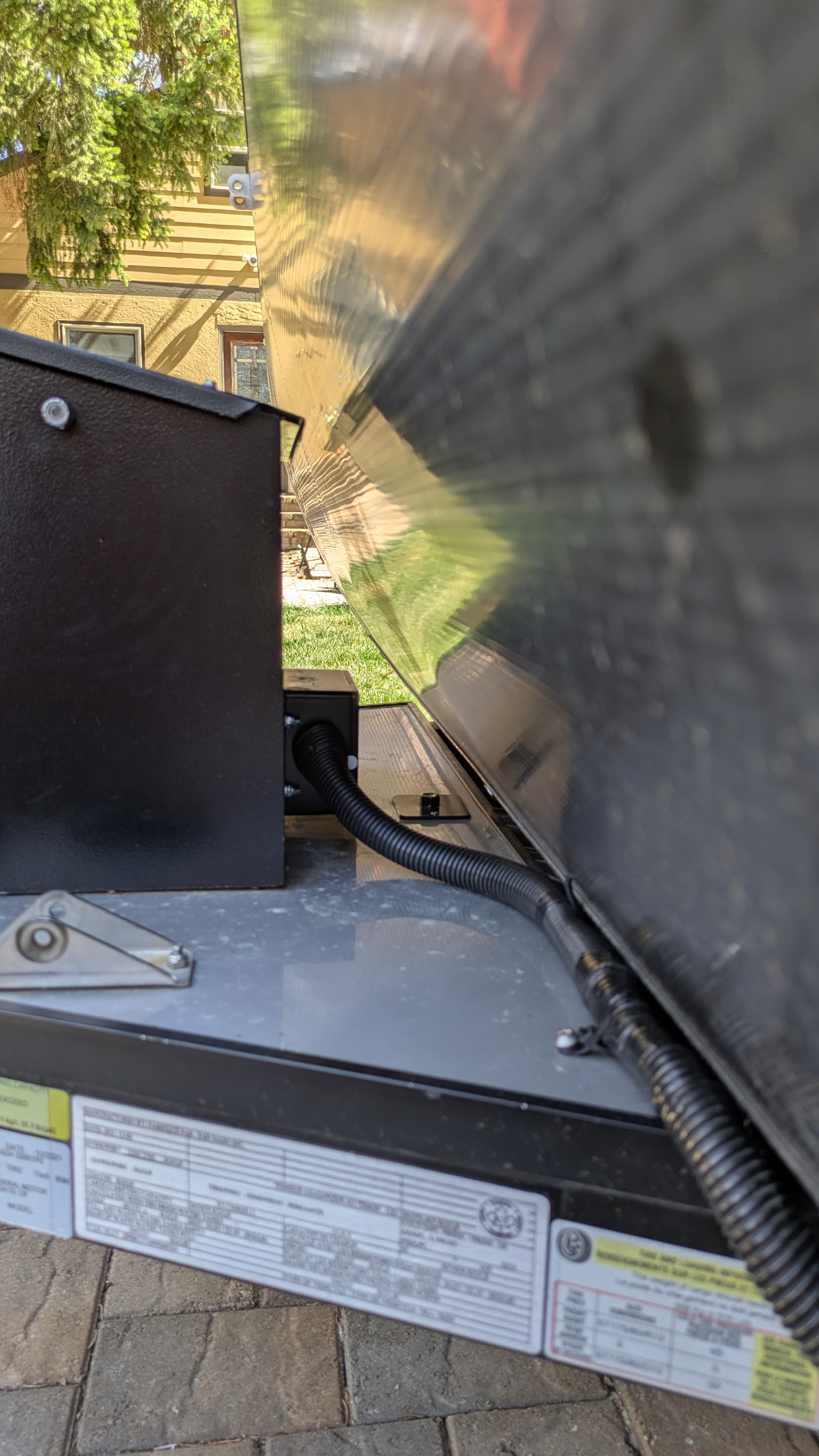
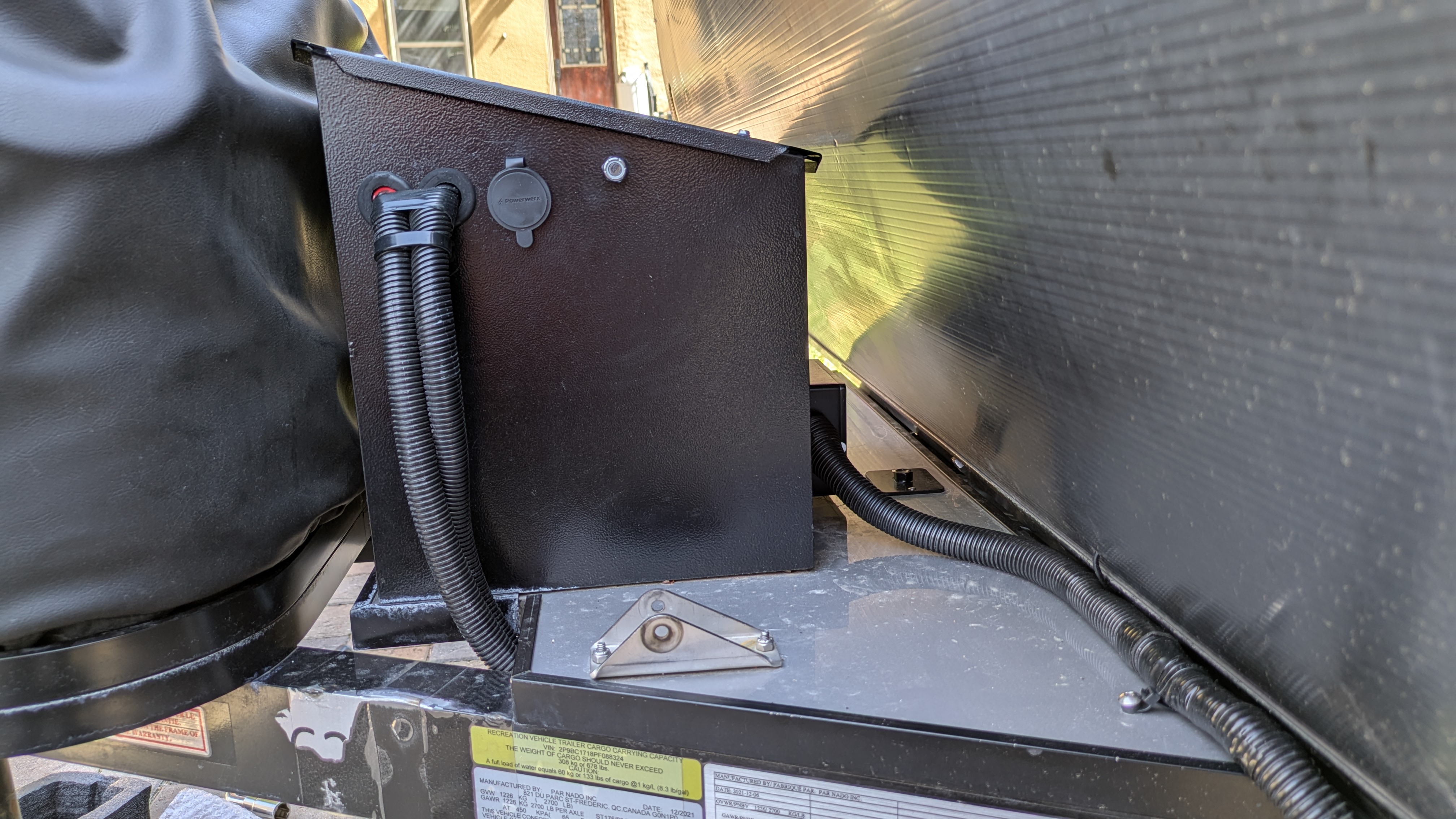
I wanted to avoid mounting it underneath the trailer for the reasons listed above. The way SC brought the 7-pin wires inside the trailer made alternative mounting locations very easy. I decided to mount it to the battery box because it’s extremely solid, perfectly vertical, and doesn’t take up room inside the trailer that could be used for other things. This thing is designed to be mounted outside the trailer so I’m not too concerned about weather and this spot on the back side of the battery box is about as protected as could be without being inside. Another reason for picking this location is that I’d prefer not to mount directly to the skin of the trailer wherever possible. And this would be a somewhat funky mechanical mount under the front skinny cushion since the trailer wall isn’t vertical in this location.
Next I had to figure out how to get the wires from the unit to the fuse box and 7-pin wires inside the trailer. This was an easy decision: the overall electrical redesign freed up the wiring running from the caravan mover to the battery box. I couldn’t use the wires themselves, they were too few and way too big, but the existing routing led perfectly from under the front skinny cushion to where I mounted the the unit on the back side of the battery box.
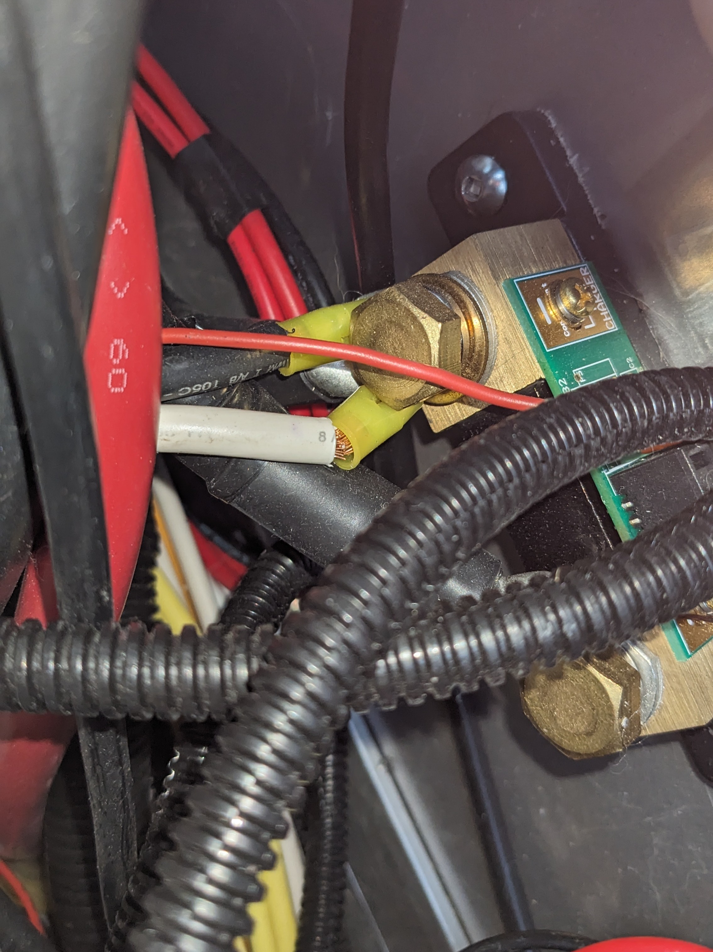
Finally, I had to find the power, ground, and the brake control signal coming from the TV and going to each wheel. SC made this super easy by bringing all the 7-pin wires, as well as the wires running to the brakes at each wheel, inside under the front skinny cushion. They enter on the right (passenger) side of the trailer (see picture below). The wire loom marked with green and yellow tape are the brake control signals going to the left and right wheels, respectively. There is corresponding colored tape at each wheel. The blue wire is +12 Vdc coming from the Outlets circuit in the fuse panel and goes to the breakaway switch outside the trailer.
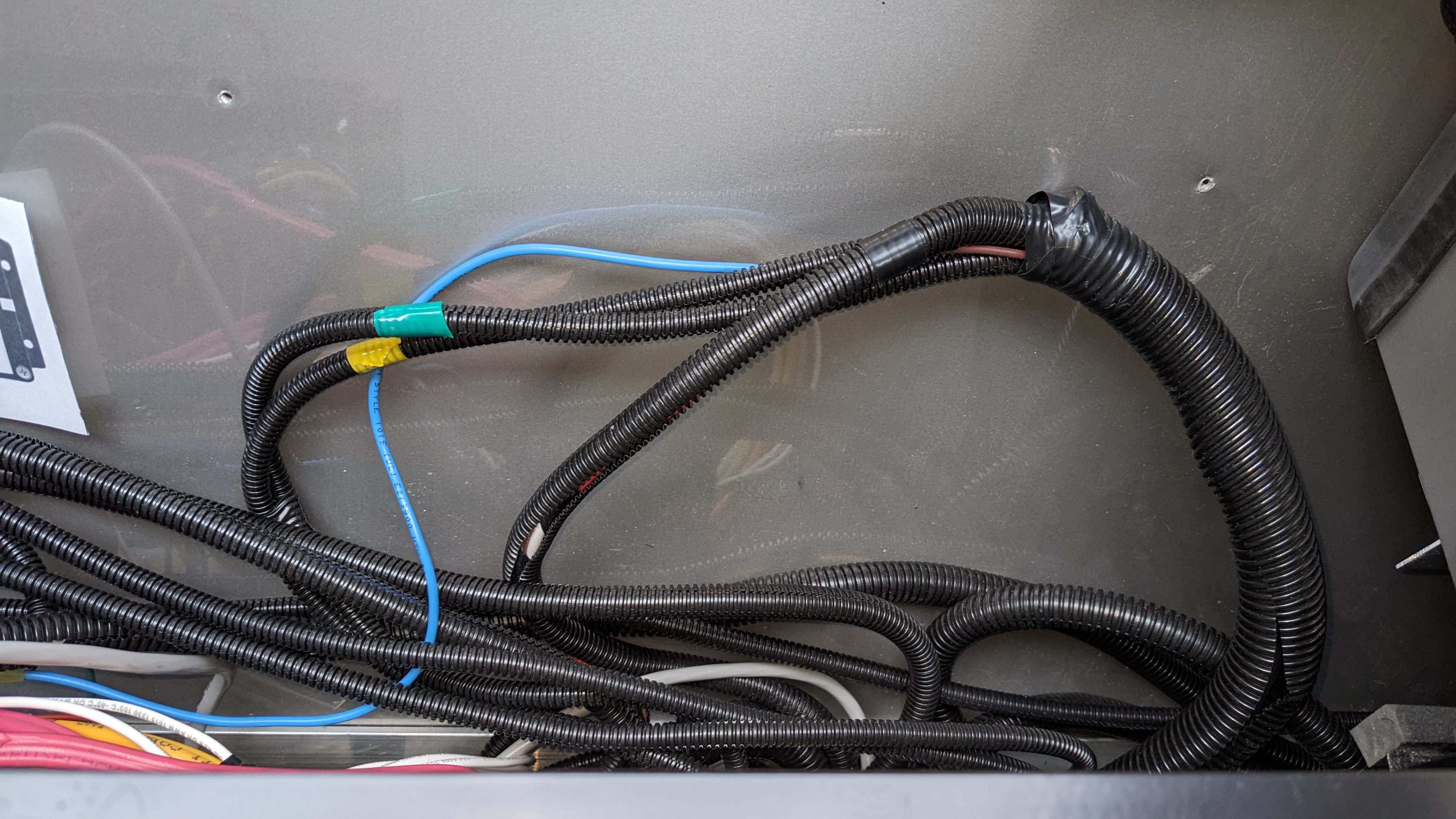
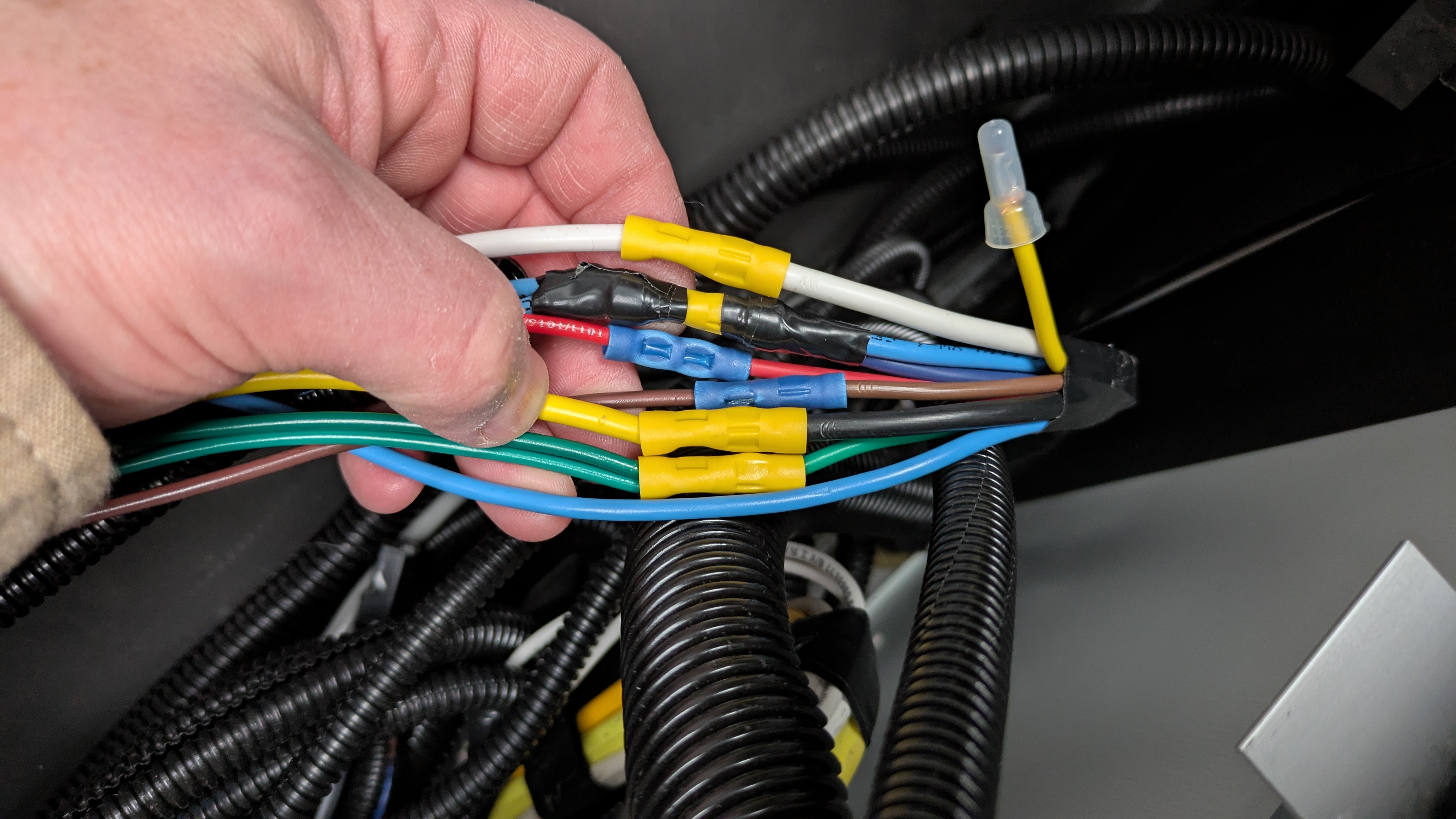
Peeling back the larger wire loom on the right revealed the individual wires. From top to bottom (only a few of these are needed for sway control):
- Yellow – Auxiliary (capped)
- White – Ground
- Blue – Brake control
- Splits to the left into left and right brake control signals routed to the wheels
- Splits to the right to the breakaway switch
- Red – Left turn / stop
- Brown – Right turn / stop
- Black – +12 Vdc
- Green – Tail lights / running lights
- Splits to the left to trailer lights on each side of the trailer
- Blue – Power from the trailer to the breakaway switch
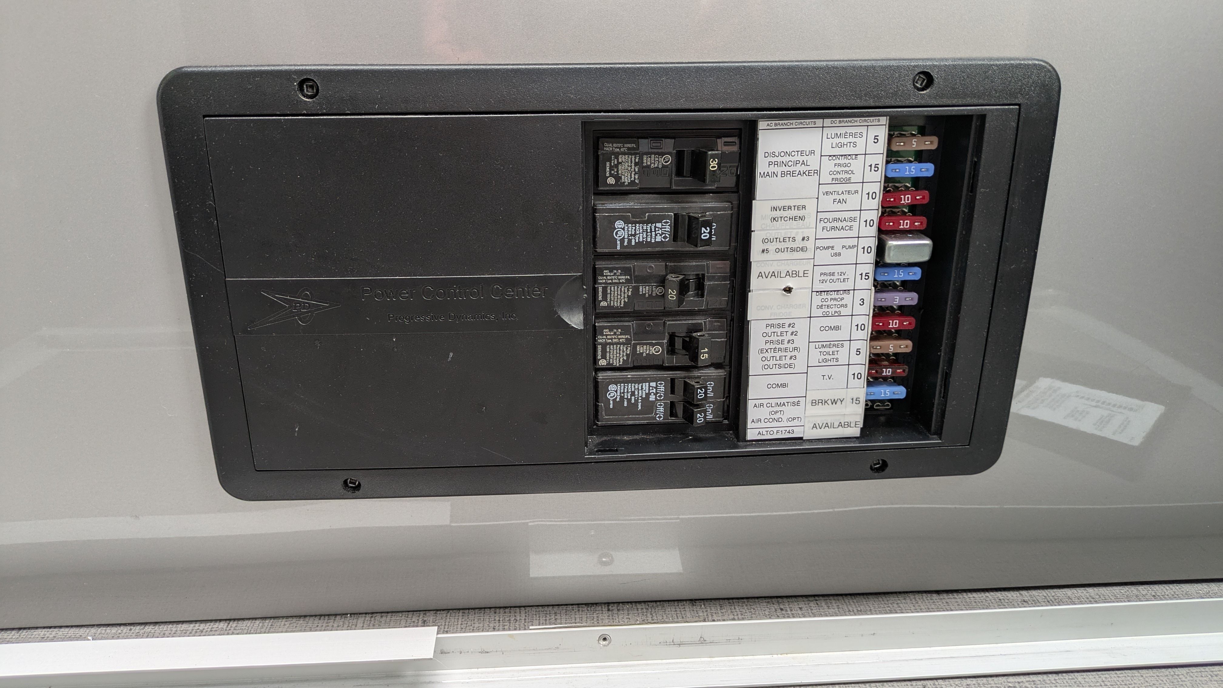
I’m not a fan of pulling power for the breakaway switch from some random circuit like Outlets. I can see why SC did it– they ran out of slots in the fuse box so they picked a circuit that was fused appropriately (15A) for the 14 AWG breakaway wire. But this decision complicates troubleshooting electrical issues. If a DC outlet pulled too much power and blew the fuse, the breakaway functionality would be inexplicably (and silently) broken as well. With the addition of the SafetyHub 150 fuse box I have no such limitation. I decided to move the Solar circuit to this new panel and repurposed the Solar fuse in the original panel for the breakaway line.
Rather than dedicating a circuit to the breakaway, I should have pulled power from the TSC circuit. That way, the TSC LED will indicate when both TSC and breakaway functionality are inoperative. I’ll make that change eventually.
Testing the system was challenging. The proper way to test, per Tuson instructions, is to short signal and ground at each wheel and note the number of flashes on the LED to confirm continuity and the correct side (left or right wheel). However to do this I’d have to disassemble the wheel that had just recently had its bearings repacked. I wasn’t willing to do that so instead I pulled the breakaway switch and verified the brakes engaged on both wheels, by jacking up each and attempting to rotate it. This verified that the brakes were getting the brake signal but not the left/right distinction. For this I made sure I was connecting the SC green signal to Tuson purple (left) and SC yellow to Tuson pink (right). And I hope SC’s labelling is correct. So far so good on a recent shakedown trip.
An annoyance of the Tuson system is that there is no indication that it’s doing anything on power-up. It’s designed to “wake up” when it sees the trailer brake signal from the TV but my TV was nowhere near when I wired this up. Fortunately pulling the breakaway switch kicks it, revealing the pulsing green LED that indicates all is well. Of course this still doesn’t tell you if left is left and right is right.
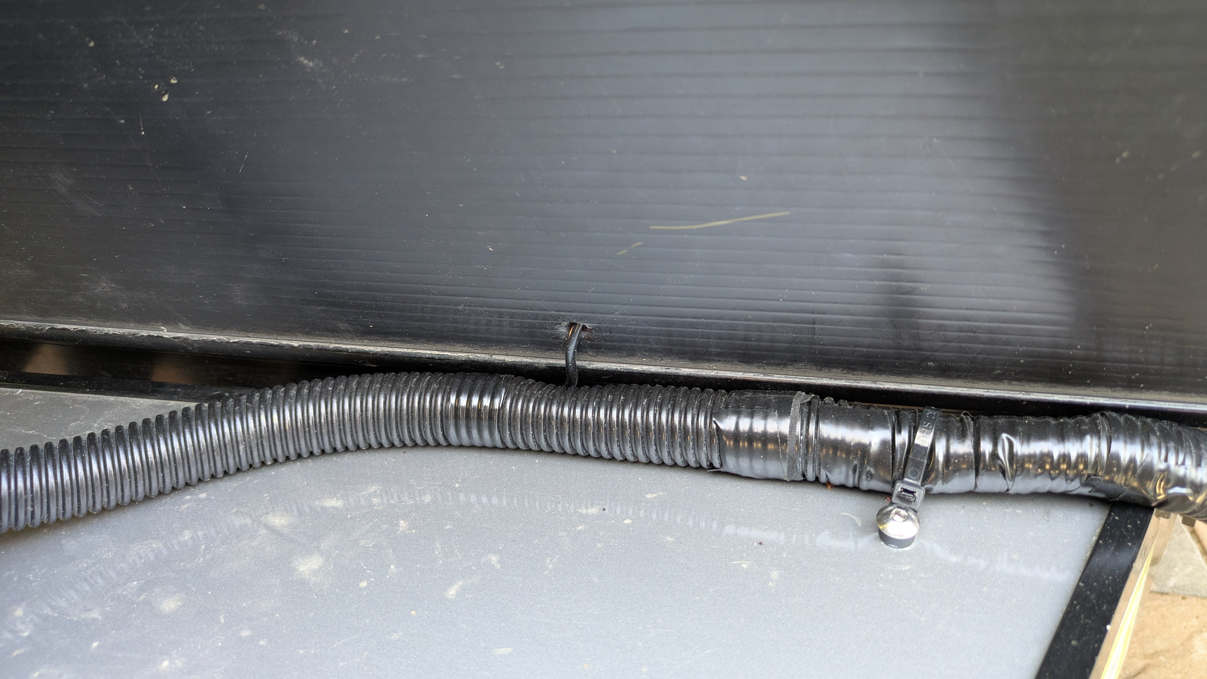
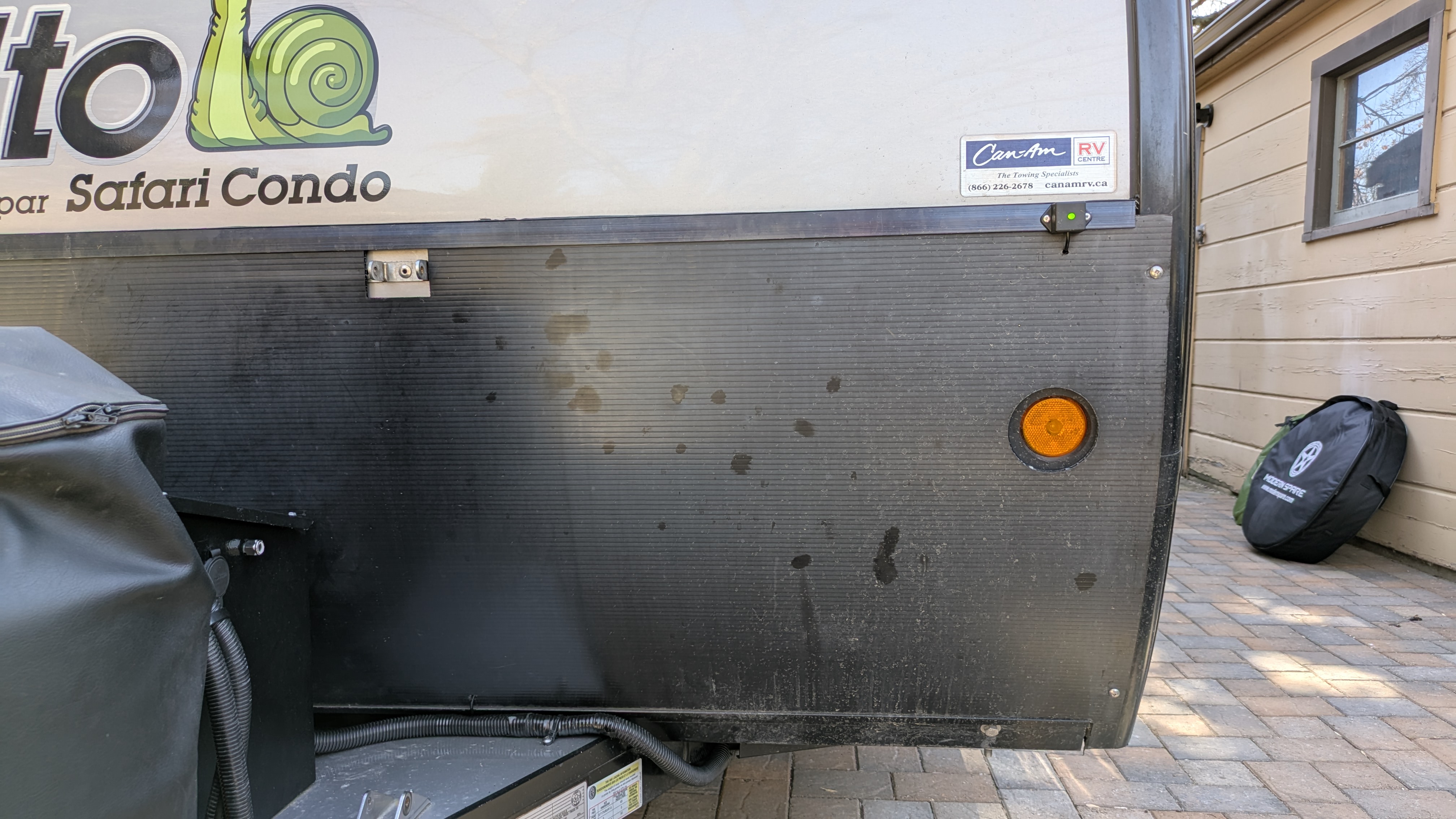
Indeed, that funky LED provides the only, very limited, visibility into what the system is doing. If I had learned about the Curt system earlier I might have opted for it because it uses a Bluetooth connection to provide this visibility. I assume it provides a lot more detail as well but I have no experience with it. But I chose the Tuson and now had to figure out where to mount the LED and how to route the cable. My original thought was to bring the cable inside the trailer along with the other wires and sneak it back outside where the driver-side front-facing trailer light is attached. Then mount the LED to the metal strip directly above the trailer light. This approach however looked too messy. Instead I kept the cable outside the trailer and poked it under the coroplast, routing the cable between it and the skin of the trailer. I mounted the LED to that same metal strip above the trailer light using two pop rivets. The connector provided by Tuson was too bulky to fit under the coroplast so I cut it off and spliced the wires together with solder and adhesive (waterproof) heat-shrink. This location for the LED proved to be perfect– easy to see from the Tesla driver-side mirror and rear camera.
Tire Pressure Monitoring System (TPMS)
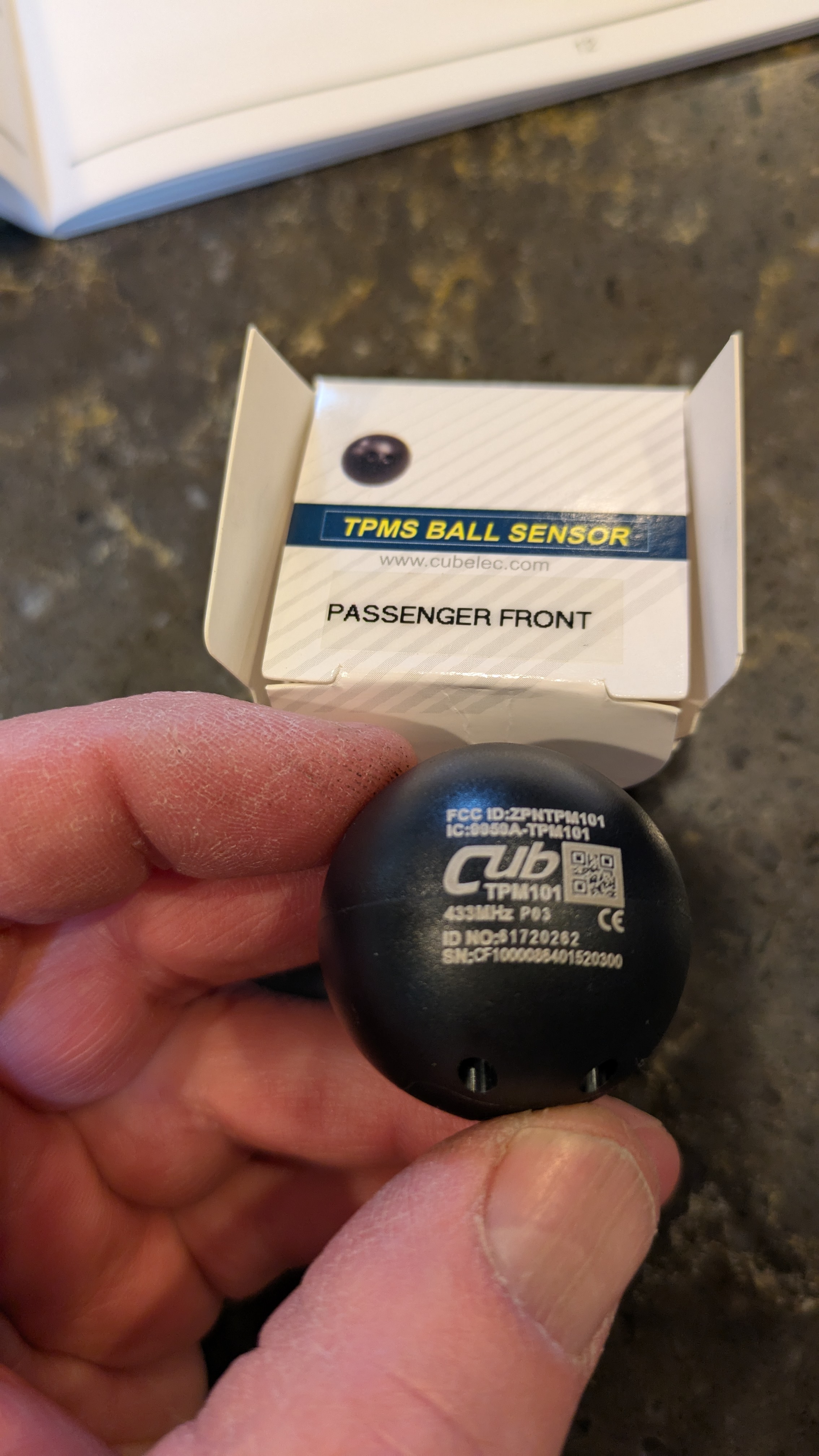
This installation was relatively simple. While sitting over the winter the stem on one of the tires failed so I had Discount Tire install the ball sensors when they replaced the stems with a (hopefully) beefier design. The stems were inexpensive and they didn’t charge for the sensor installation since they had to remove the tires from the rims to replace the stems.
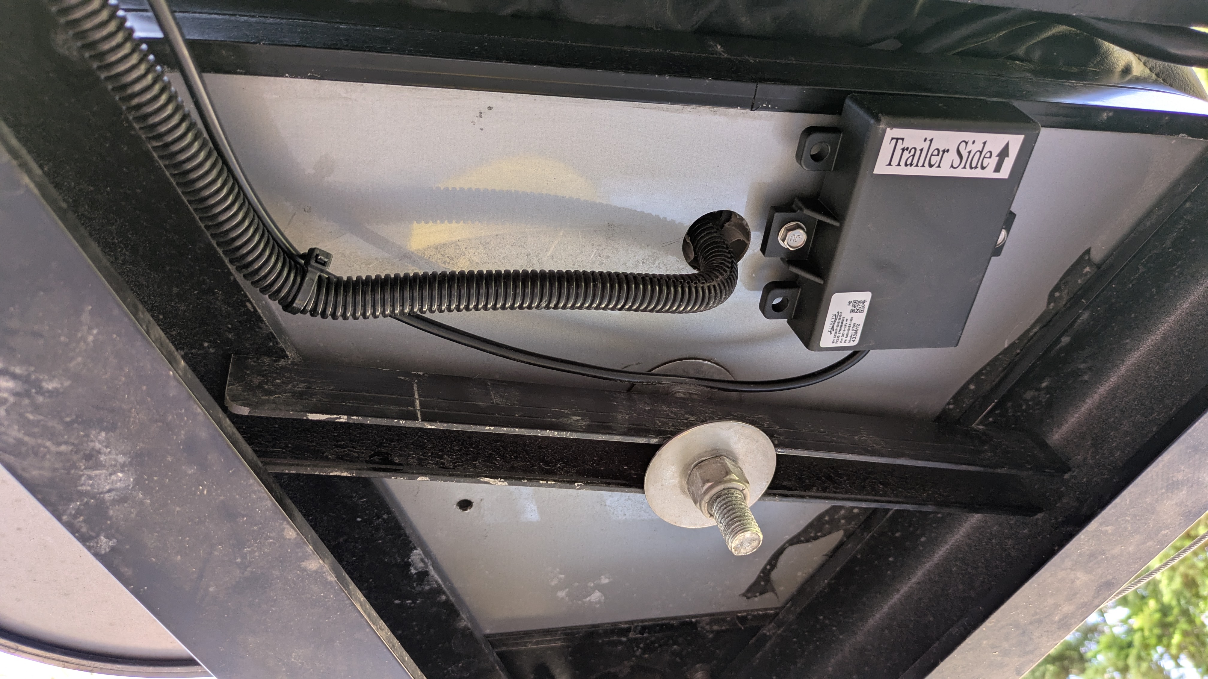
It’s possible that with such a small trailer I wouldn’t need a signal repeater but it came with the kit and I was overhauling the electrical system anyway. Underneath the propane bottles seemed like a natural location and made it easy to route the cable to the wire bundle for the sway controller and inside the trailer. The current draw is very low but my goal is for every load to be accounted for by the battery monitor so I wired it into the Blue Sea Systems fuse panel.
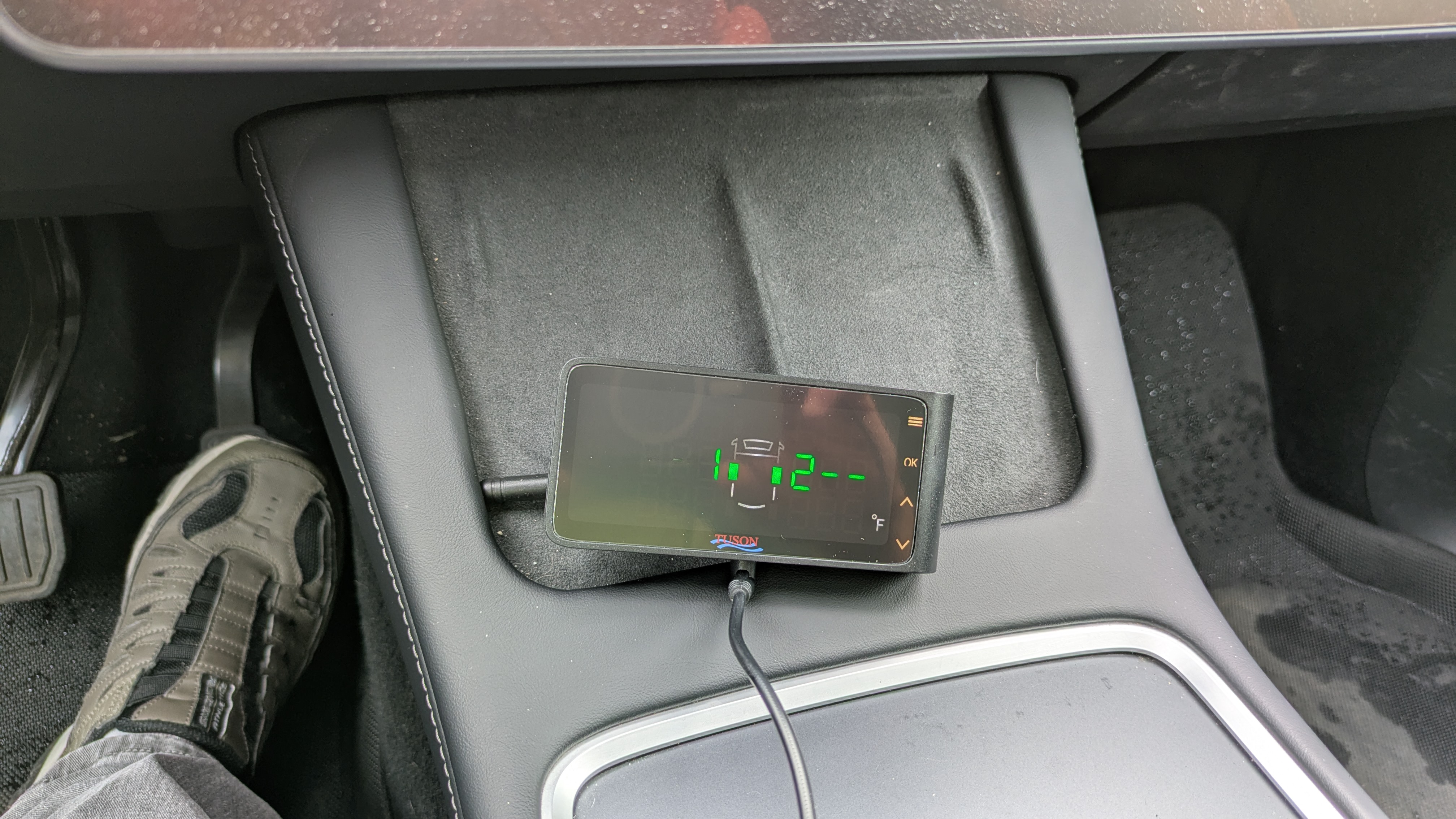
One (minor) reason I chose the Tuson system over others is that in addition to tire pressure and temperature, it reports the voltage of the trailer battery. But I forgot that I already have that information on my phone from either the Victron BMS or solar controller– the Bluetooth signals make it inside the cabin of the TV just fine. Oh well, it’s like having a clock in every kitchen appliance, each reading a slightly different time.
In our shakedown trip the TPMS system worked well and I think will be very reliable.
External Solar
I’m not sure yet what portable solar panel I will purchase. I’m eying 220W panels as well as a new modular 500W panel from EcoFlow– this choice will determine the solar controller I’ll need. We don’t have any boondocking plans this season that need the additional solar power so we’ll probably purchase the panel and controller next season. But while mucking around with the trailer wiring I might as well install the connector and bring the wires to the location I plan to install the controller.
The electrical redesign freed up a pair of 8 AWG wires running from the batteries to the original fuse panel. The battery box is a perfect place to install the external solar connector and the controller will be installed near the fuse panel so I just re-used the wires– pretty simple. 8 AWG is overkill but doesn’t hurt anything, will just have to crimp on a short section of 10 AWG wire for the connector. Removing the CM wiring left a hole in the battery box just slightly too small for a waterproof bulkhead PowerPole connector so I used a step drill to widen it and installed the connector. For now I’m leaving it unconnected.
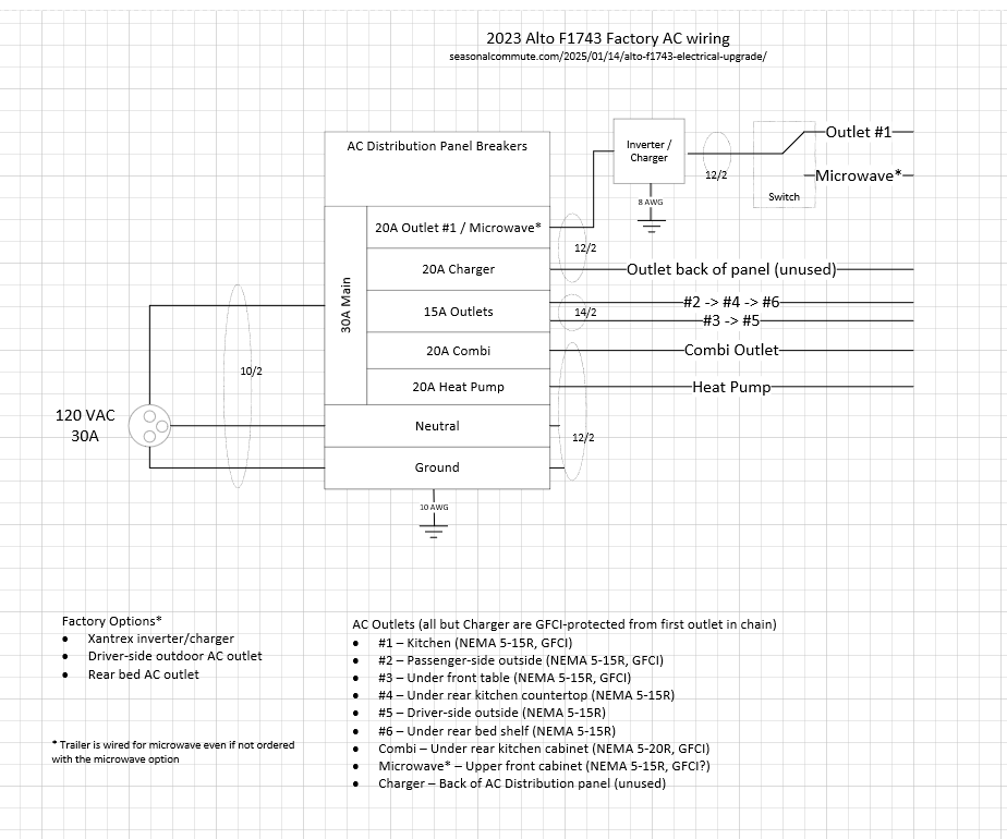
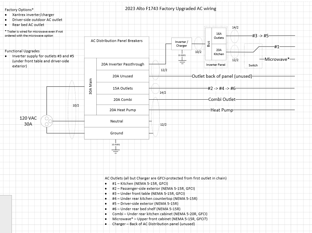
Inverter Power for Outside Outlet
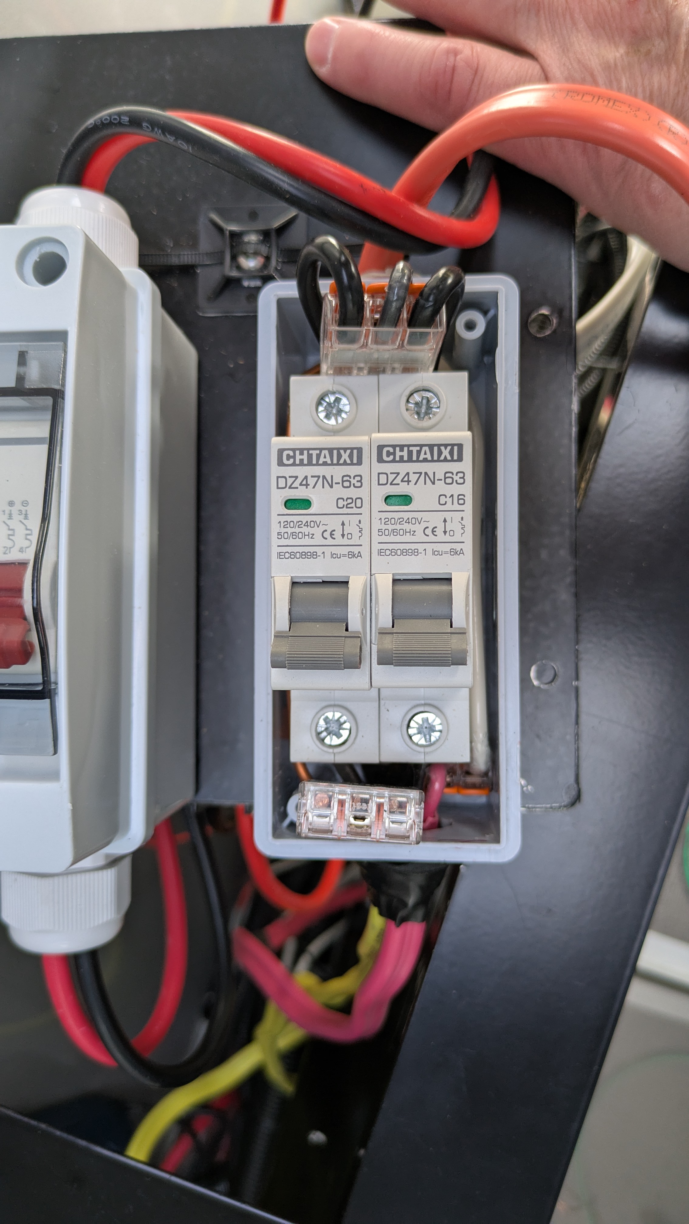
This was a fairly simple change. Instead of running the inverter AC output directly to the microwave/outlet #1 rocker switch in the kitchen, I ran it to a new 2-breaker housing. I ran a 20A circuit in that housing to the microwave/outlet #1 switch to achieve the same functionality as before. And I moved the source of the outlet under the front table from the original AC breaker to a 15A breaker in this new breaker box. This circuit also feeds the driver side external outlet, giving me inverter power for both. Because worst-case it’s possible for this new breaker box to draw more than 20A, I beefed up the Romex from the inverter to 10 gauge.
The hardest part of this mod was wiring the miniature breaker box. This thing was just barely big enough to handle the necessary wire and connectors. Bringing 10 gauge Romex into the box didn’t help. I used Wago connectors instead of traditional wire nuts, I don’t think this would be possible with the latter.
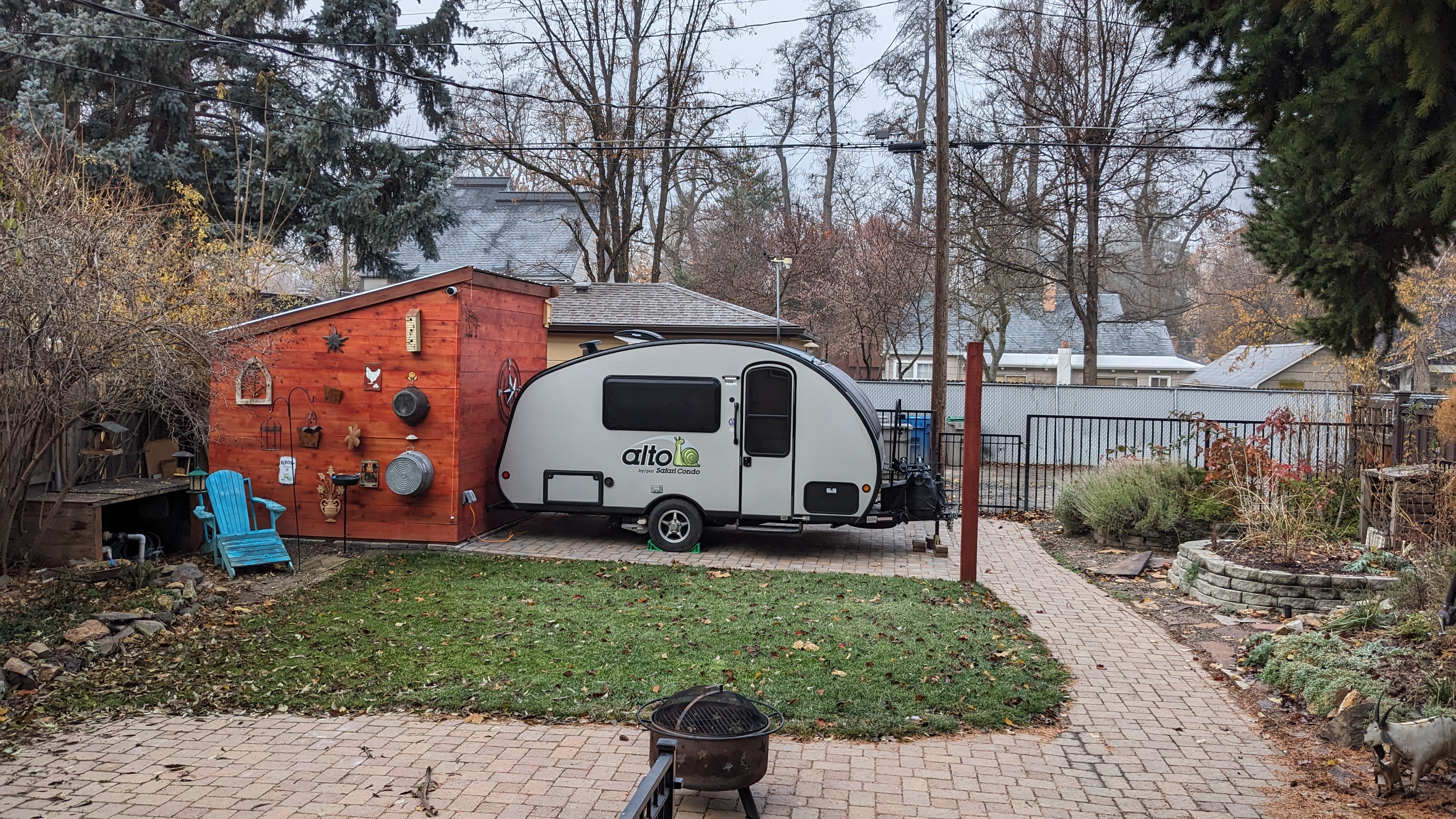
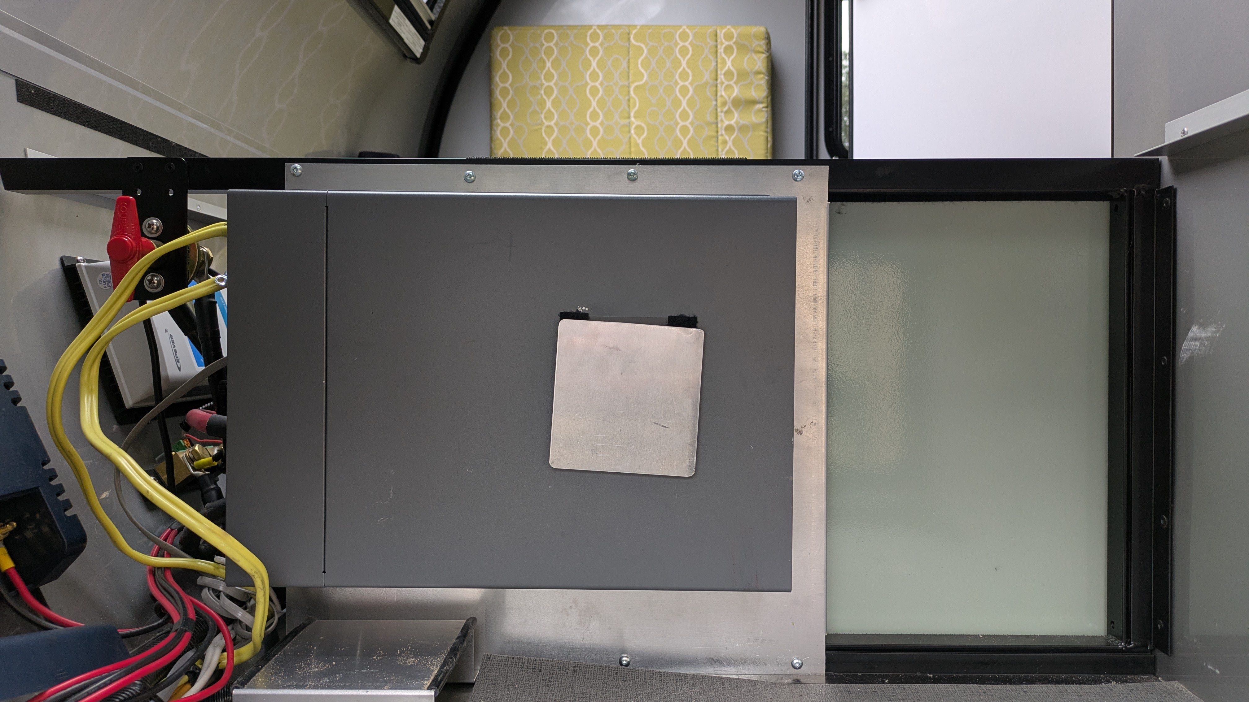
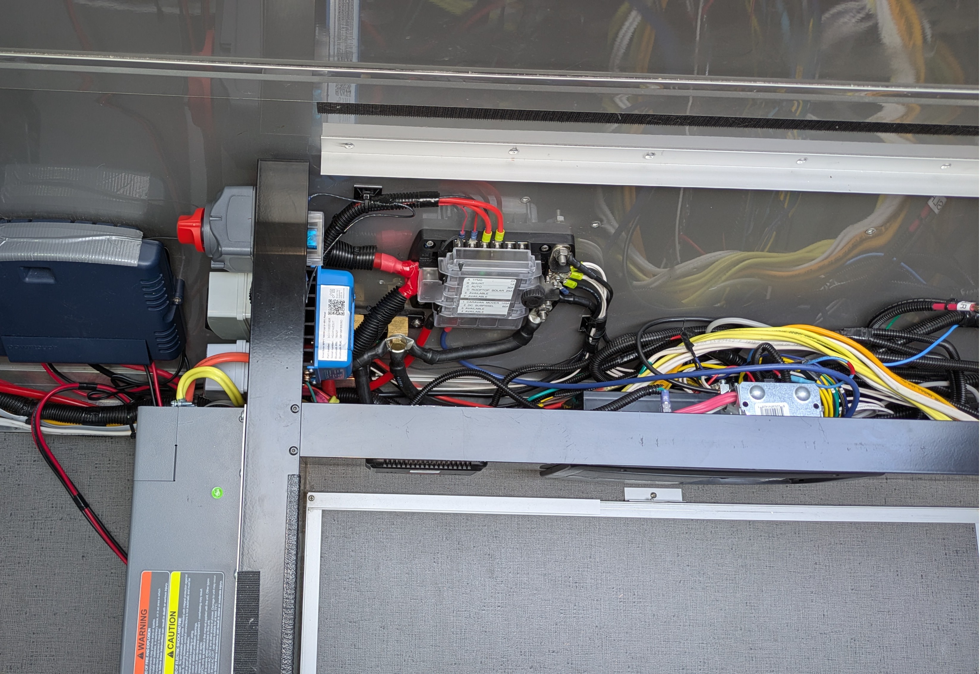
Finished Product
Here are some pictures of the completed project.

Lessons Learned
- I love the mechanical design and build quality of the Alto trailers. Factory electrical, not so much.
- Curt sway control might have been a better choice than the Tuson system. I prefer the Tuson’s mounting requirements (funky LED aside) but would like more visibility into what the system is doing. I’m not convinced differential braking is as important as Tuson claims.
- If I were to go through this exercise again I might move the location of the smart shunt to free up some space around the other components. And probably raise the solar controller a bit. Digging back in to some of these components is a bit of a pain.
- Upgrading the solar controller from Epever to Victron was well worth it. The Victron is a joy to use, beginning with a solid, compact mechanical design and ending with a rare example of a well designed phone app. It’s so much better that I won’t try to sell the Epever because in good conscience I’d have to recommend purchasing a Victron instead. I can’t think of a reason why you’d ever want to choose the Epever even as a replacement if the original died. But if someone wants this thing, let me know.
- One down side to running all the DC power through a single 2/0 gauge cable pair is that under maximum inverter load, there is enough voltage drop to noticeably dim the LED lights. I see this when running the induction stovetop at full power. A microwave would do the same. The Xantrex and other electronics don’t seem to mind. I’ve yet to measure the drop.
Wiring Diagrams
Parts List
Doesn’t include probably a couple hundred additional dollars in miscellaneous small parts and tools. I had a lot of the necessary tools including the rivet nut setter and smaller crimpers / strippers but purchased a hydraulic cable lug crimper for the big wires and a label maker.
By ordering sway control and TPMS at the same time, I met Tuson’s $1,000 threshold for receiving a 25% discount. This discount was a pleasant surprise, it’s undocumented as far as I can tell.
| Component | Price ($USD) | Weight (lb) |
| Victron SmartSolar MPPT 100/20 | $90 | 1.3 |
| Tuson TSC-1000 sway control | $585 | 1.4 |
| Tuson TPMS4W-BALLSENS TPMS | $479 | .5 |
| Kohree DC disconnect switch | $12 | .6 |
| CNLonQcom solar isolator switch | $23 | .5 |
| Blue Sea Systems SafetyHub 150 fuse block | $86 | 1.7 |
| In-Line Fuse Holder | $14 | .1 |
| PowerX Anderson PowerPole connector | $27 | .1 |
| Chtaixi 20A AC mini circuit breaker | $8 | .1 |
| Chtaixi 16A AC mini circuit breaker | $8 | .1 |
| 2-way AC Breaker Housing | $11 | .1 |
| 8″ x 8″ x 1/8″ Aluminum Sheet | $6 | .6 |
| Removed wire and connectors | (3.6) | |
| Epever Solar Controller | (2.2) | |
| Original battery disconnect | (.6) | |
| Tuson discount (25%) | ($266) | |
| Total | $1,083 | .7 |
Torque
| Item | Torque |
| Victron smart shunt | 21 Nm |
| Victron solar controller | 0.75 Nm |
| Kohree battery disconnect switch | Unknown |
| CM battery disconnect | Unknown |
| Xantrex inverter/charger DC power lugs | 10 Nm |
| Xantrex inverter/charger ground lug | 2.6 Nm |
| Blue Sea fuse box, low current connector screws | 2.03 Nm |
| Blue Sea fuse box, AMI screw-in fuses | 3.05 Nm |
| Blue Sea fuse box, high current connector studs | 20.34 Nm |
| Volthium battery terminal | 10 Nm |